chipKIT Tutorial 6: Inter-Integrated Circuit (I2C) communication
|
|
I2C or IIC (Inter-Integrated Circuit) is a simple bidirectional serial interface, which requires only 2 signal lines for data transfer. It was originally developed by Philips in 1980′s to provide easy on-board communications between a CPU and various peripheral chips in a TV set. Today, it is widely used in varieties of embedded systems to connect many low speed peripherals, such as external EEPROMs, sensors, LCD drivers, port expanders, real-time clocks, etc, to the host microcontroller. In this tutorial, we will explore the chipKIT Wire Library for establishing an I2C communication link between the chipKIT Uno32 board and two I2C sensors. The Uno32 board receives the sensor outputs through the I2C link and displays the results on the serial monitor window on the computer screen.
I2C communication demo
Theory
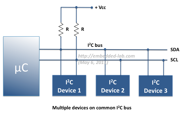
An I2C bus consists of two signal lines called SDA (data) and SCL (clock). Just line Arduino Uno, the chipKIT Uno32 board offers the SDA and SCL connections via analogue input pins A4 and A5 respectively. Each device connected to the I2C bus is software addressable by an unique 7-bit address. Multiple I2C devices can be connected to the same I2C bus as long as they have different addresses. A simple Master and Slave relationship exist at all times between the communicating devices. The Master device initiates a data transfer, generates clock signals and terminates the transfer. Any device addressed by the Master at any time is considered a slave. Both SDA and SCL are open-drain lines, and therefore, require two pull-up resistors during operation. A more detail look of the I2C Bus protocol and how the exchange of information takes place between Master and Slave has been discussed in one of my previous tutorials, Inter-Integrated Communication in PIC MCU. So I am not going to repeat that here again.
Source: http://embedded-lab.com/blog/?p=2583
In this tutorial, we are going to experiment with two digital temperature sensors that support I2C communication. They are Maxim’s DS1631 and Microchip’s TC74 devices.
The DS1631 is a digital thermometer that provides configurable 9-, 10-, 11-, or 12-bit temperature readings over a -55°C to +125°C range. Some of its features are highlighted below. The 7-bit I2C address of DS1631 is configurable by hardwiring the A0, A1, and A2 pins to VCC (1) or ground (0).
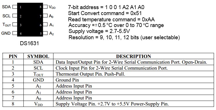
DS1631 features
Similarly, the TC74 device is also a serially accessible digital temperature sensor that provides a temperature measurement as an 8-bit word. The resolution is thus 1 degree Celsius. Its features are highlighted below. It should be noted that there are no external pins for configuring the I2C address. This means that the 7-bit I2C address of TC74 is fixed and set by manufacturer. Eight versions of TC74 are available, namely TC74A0 through TC74A7, with different I2C address values. I am using TC74A0, which has the 7-bit address fixed to 1001000 (0x48).
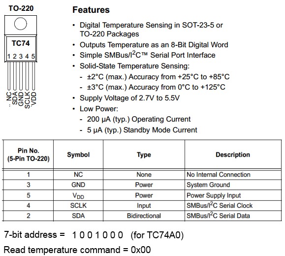
TC74 features
Please read the datasheets of DS1631 and TC74 for more information on these devices.
Circuit Setup
Perhaps you have noticed that the four most significant bits of the I2C addresses of DS1631 and TC74A0 are same (1001). The remaining address bits of TC74A0 are fixed (000). But the same bits are configurable for DS1631 through its hardware pins. We will ground the pins A1 and A2, and pull-up pin A0 to VCC so that the I2C address of DS1631 would be 1001001 (0x49). We build the following circuit on a breadboard and power it through the 3.3V power supply from the Uno32 board. The SDA and SCL signal lines are connected to analog input pins A4 and A5, respectively. Note that the jumpers JP6 and JP8 must be placed in the RG3 and RG2 position in order to use these pins for I2C operation. See Exploring chipKIT Uno32 for more details on the functions of various shunt jumpers on the Uno32 board. The pull-up resistors for the I2C signal lines can be of value anywhere between 1K and 10K, at least for this experiment.
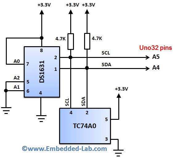
Circuit diagram for connecting DS1631 and TC74A0 to chipKIT Uno32
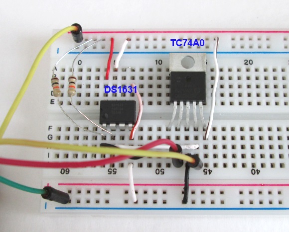
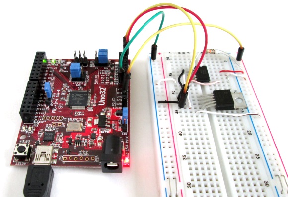
Complete circuit layout on breadboard
chipKIT Sketch
The Arduino’s standard Wire library is also implemented in MPIDE, which allows chipKIT Uno32 to communicate with I2C devices. The Wire library uses 7 bit addresses for addressing slave devices on the I2C bus. Following are the main functions available in the Wire library.
Wire.begin() initializes the Wire library and configures analog pins A4 and A5 as I2C pins. This should normally be called only once.
Wire.beginTransmission(address) begins a transmission to the I2C slave device with the given 7-bit address.
Wire.send(data) sends data to the slave device.
Wire.requestFrom(address, count) is used by Master to request a specific number of bytes from a slave device.
Wire.receive() is used by Master to retrieve a byte that was transmitted from a slave device after a call to Wire.requestFrom(address, count)
Wire.endTransmission() ends the data transmission.
Wire.available() returns the number of bytes available for retrieval with Wire.receive().
More details on the chipKIT specific Wire library can be found here.
Here’s the sketch written for requesting temperature readings from the DS1631 and TC74A0 devices and display them on the Serial Monitor window.
/* Tutorial 6: I2C communication demo Description: Explore the I2C serial communication protocol and interface two I2C slave devices to chipKIT Uno32 using a common I2C bus. Two devices: DS1631 and TC74A0 temperature sensors. Board: chipKIT UNO32 Connect SDA to Arduino pin A4 (SDA) Connect SCL to Arduino pin A5 (SCL) Written by: Raj Bhatt (April 2014) www.embedded-lab.com */ #include <Wire.h> int DS1631_Address = 0x49; // 7-bit I2C address for DS1631 int TC74A0_Address = 0x48; // 7-bit I2C address for TC74A0 // setup loop void setup(){ Serial.begin(9600); Serial.println("IIC Test: Temperature sensors"); Wire.begin(); } // Main Loop void loop(){ float temp1 = Read_Temp_DS1631(); Serial.print("DS1631 reading: "); Serial.print(temp1, 4); Serial.println(" degC"); float temp2 = Read_Temp_TC74A0(); Serial.print("TC74A0 reading: "); Serial.print(temp2, 2); Serial.println(" degC"); delay(1000); } // Function sub-routine for reading temperature from DS1631 float Read_Temp_DS1631(){ float tempC1; int MSbyte1, LSbyte1; Wire.beginTransmission(DS1631_Address); Wire.send(0x51); // Send Start Convert command Wire.endTransmission(); delay(1000); // Wait until temperature conversion is done Wire.beginTransmission(DS1631_Address); Wire.send(0xAA); // Send Read Temperature Command Wire.endTransmission(); Wire.requestFrom(DS1631_Address, 2); // Request two temperature bytes while(Wire.available()) // { MSbyte1 = Wire.receive(); LSbyte1 = Wire.receive(); } Wire.endTransmission(); LSbyte1 = LSbyte1>>4; tempC1 = (float)MSbyte1 + (float)LSbyte1*0.0625; return tempC1; } // Function sub-routine for reading temperature from TC74A0 float Read_Temp_TC74A0(){ float tempC2; int MSbyte2; Wire.beginTransmission(TC74A0_Address); Wire.send(0x00); // Send Read Temperature command Wire.endTransmission(); Wire.requestFrom(TC74A0_Address, 1); // Request a temperature byte while(Wire.available()) // { MSbyte2 = Wire.receive(); } Wire.endTransmission(); tempC2 = (float)MSbyte2; return tempC2; } |
Output
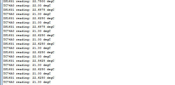
Upload the above sketch to the Uno32 board and then open the Serial Monitor window to display the temperature readings from the two sensors.
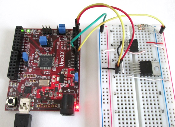
Complete experimental setup
The two temperature sensor readings seem to agree within 2 degree Celsius. DS1631 has better accuracy and resolution than TC74A0.
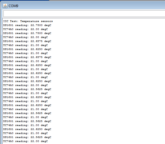
Temperature outputs from DS1631 and TC74A0
|
|
Dear all,
First of all, I apologize if this place is the wrong one to post this kind of comments, and maybe you could redirect me toward a best suited place.
Thanks a lot for this very interesting tutorial. Unfortunately, I’m unable to make I2C work using a ChipKit UNO32 alongside with the MPIDE 0150 under Windows (see minimal code example below). I did the same test with a Arduino UNO and it works perfectly. It is a simple I2C scanner used with a ITG-3200 breakout. It involves only ” Wire.beginTransmission” and ” Wire.endTransmission” functions.
I would be really gratefull if you could provide me any help.
With my best regards.
Marc
// BEGIN CODE
#include
char id=0;
void setup()
{
Serial.begin(9600);
while (!Serial);
Wire.begin();
}
void loop()
{
byte error;
byte address;
int nDevices;
Serial.println(“\n[I2C Scanner]”);
Serial.println(“Scanning…”);
nDevices = 0;
for(address = 1; address < 127; address++ )
{
Wire.beginTransmission(address);
error = Wire.endTransmission();
if (error == 0)
{
Serial.print("I2C device found at address 0x");
if (address<16)
Serial.print("0");
Serial.print(address,HEX);
Serial.println(" !");
nDevices++;
}
}
if (nDevices == 0) {Serial.println("No I2C devices found\n");}
else {Serial.println("Done\n");}
delay(5000) ;
}
// END CODE
What a great tutorial, thank you! I’ve had a Uno32 since they came out, but I’ve not yet had a chance to play with i2c. Your tutorial, along with your clean graphics and photos, really help make things extra clear. Thank you, your work is appreciated!