A DIY I/O board for experimenters
|
|
I remember when I first stepped into the world of embedded electronics, I started with doing some basic microcontroller circuits on a breadboard. Breadboard is a wonderful tool for prototyping and testing circuits. When the test of a circuit is successful, you can dissemble it and the board is ready for a new circuit. While working on breadboard was a great learning experience, it was little bit frustrating sometimes when you realized after dissembling a circuit that you have to put it together again or just a part of it for your new project. It happens very often because most embedded projects require some common stuff, basically I/O devices such as switches, LEDs, LCD display, buzzer, etc. Connecting these things on the breadboard for every new project is time consuming and boring. If you are a newbie and having the similar experience, here I suggest a general purpose I/O board that will not only reduce your prototyping time but also free up plenty of space on the breadboard for your project.

DIY I/O board for experimenters
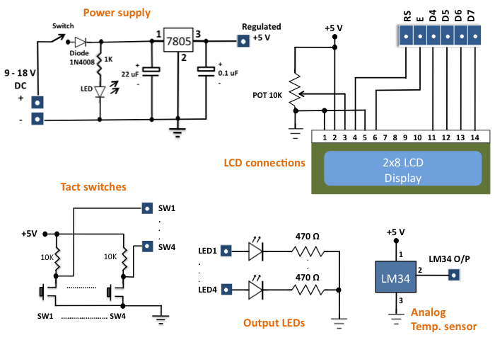
The construction of this board is very simple. You can solder basic I/O devices of your choice (that you use more frequently) on a general purpose perforated board and provide access to them through headers. The board that I constructed is shown below. It has got an LM7805 IC that provides a regulated +5 V power supply to rest of the devices on the board. A 16-pin female header is a plug-in for an HD44780-based alphanumeric LCD. The four data pins (D4-D7) and two control pins (Register Select, RS, and Enable, E) of the LCD are accessible through female headers, as shown on the bottom left part of the board. A potentiometer is also available on the board to adjust contrast of the display.

Construction of a general purpose I/O board
Four tact switches, four LEDs, and one coil buzzer serve as basic input and output devices. In this particular version, I have also added a LM34DZ temperature sensor device along with an I2C compatible serial EEPROM (24LC512). There’s plenty of prototyping space available for extending the functionality of the board in future.

I/O board with LCD plugged-in
The circuit diagram of this project is very simple. There is nothing special as each component is independent and is not connected to any other component. The only common thing in them is all of them share the same Vcc and Gnd terminals. I have provided the following schematics for reference purpose.

Circuit diagram of the I/O board

I2C device and buzzer connections

Complete circuit on a perforated circuit board

Bottom view of the I/O board
Testing the board

PIC16F1827 on breadboard reads LM34 output and displays temperature

Testing the I/O board with Amicus18
I tested the LCD with Amicus18 board, and the 3.3 V logic output of the Amicus18 processor successfully drove the LCD data and control pins (although the LCD is powered by +5 V supply).
Summary
We discussed about a general purpose I/O board that is easy to construct and is very useful for rapid prototyping of microcontroller-based projects. The board can be made more versatile by adding further devices like RTC, seven segment LED display, digital potentiometer, etc. All the necessary pins of the devices on the board are accessible through female headers that allows easy connection of the board to a breadboard circuit or other development boards (Arduino and Amicus18, etc) using male jumper wires.
|
|
hello! for this project, may I use the USB standard for the power supply? How i have to modify the original scheme? thanks!
if u are quite confident the usb port that you have supplies 5 Volt, it is easy: look at the circuit of the psu where is says: +5V regulated power. That is where you feed in yr usb power.
I made this circuit .it is working .but the problem is the lcd showing value is 5 Celsius lager than real value.i tried to reduce that in program but couldn’t .please say me how to reduce the displaying value of ldc 5c of present value.
daminda
Daminda, as there is no answer yet to yr question, i hope you found a solution, but if not, it isnt so difficult. I would think just in general temp=temp-5 should do the trick. but i guess you probably tried that alreday. I didnt see any software so i am not sure ‘how to do it in the program’, but a simple subtraction seems the way to go
I`m thinking of building something similar to this.
Where did you get sockets that the breadboard wire links plug into?
Do you have a link?
Thanks.
You can find them at many stores. I got them from tayda.
http://www.taydaelectronics.com/connectors-sockets/sockets/sip-sockets.html
I like all this, I will my own board like the one you showed
really nice! I am goning to make it! Thanks
yep is really boring making every thing again :S
Someone please help me with simple diagram circuit to mesure capacitance
How about this
http://embedded-lab.com/blog/?p=1747
I really wish you showed a photo of the backside of the board. As someone who knows extremely little about electronics, but wants to learn, these things are important. Awesome post!
Hey Kyle,
I just added the bottom side views of boards.
That’s a good idea. I didn’t know what could i do with some stuff “archived” in home. Thanks
Cooooooool