Amicus18: Arduino-style platform for PIC fans
|
|
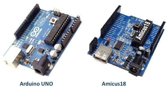
Arduino needs no introduction; it is an easy-to-use yet powerful open source embedded system development platform that has gained huge amount of popularity in past few years, specially among hobbyists. The standard hardware consists of an 8-bit Atmel AVR processor with on-board headers providing access to its I/O pins. The processor is pre-programmed with a serial bootloader that simplifies the uploading of user programs to the on-chip flash memory without the need of any external programmer. Because of its low cost, user-friendly software development environment (open-source C/C++ like programming platform), rich set of libraries, and tons of resources available online, Arduino has become a common choice for electronics hobbyists these days. Hundreds of plug-in application boards, called Arduino shields, are also commercially available to extend the functional capabilities of the Arduino board. The growing influence of Arduino inspired others to build a number of different versions of it. Amicus18 is also an Arduino-inspired embedded system development platform designed by Les Johnson and introduced by Crownhill Associates; however, it uses a Microchip PIC processor instead of the AVR microcontroller. This article reviews the features of the Amicus platform.

AMICUS18 has the same form factor as the Arduino
What is on the Amicus18 board?
The Amicus18 board uses the Microchip PIC18F25K20 microcontroller, which has 32768 bytes of flash memory, 1536 bytes of RAM, and operates at 64MHz. The dimensions of Amicus18 board have been kept exactly the same as the Arduino so that the massive number of low cost shields that are available for Arduino could also be used with the Amicus18 board. All the I/O pins of the microcontroller are accessible through on-board female header pins. Remember that several I/O pins of PIC18F25K20 microcontroller are multiplexed with an alternate functions from the internal peripheral modules, such as ADC, PWM, comparators, USART, I2C, and SPI. The functionality of an individual pin can be chosen out of these many through software. The figure below shows the layout of the components and headers on the board. The header pins are labeled very well on the actual board for easy identification.

Amicus18 development board layout (Source: Amicus18 hardware manual)
Communication with the Amicus18 board is through an USB interface, which presents itself as a standard serial port on the PC. The preloaded bootloader (which occupies the very top 128 bytes of the program memory) allows you to program the microcontroller directly through this port. However, if the need arises, an ICSP (In Circuit Serial Programming) interface is provided on the board to program the microcontroller with an external programmer. The board contains USB A-type receptacle (not very standard), which means you need A Male to A Male type USB cable to connect the board to the host PC.
It is important to note that the PIC microcontroller provided with the Amicus18 board is 3.3 V type, which means the logic high I/O voltage is also 3.3 V. This allows the Amicus18 board to directly interface with modern devices like 23K series SPI RAM, SD/MMC card, and ENC28J60 (Ethernet controller), which all operate at 3.3 V. However, it could be an issue while interfacing with some other devices that strictly operate at 5 V. Most 5 V devices might accept 3.3 V as logic high input, but their 5 V outputs may not be acceptable to the I/O pins of PIC18F25K20, as they are not tolerant to this voltage. So care must be taken while doing so. For example, writing to a 5 V HD44870 based character LCD module is OK, but reading data from the LCD could be harmful to the PIC18F25K20 I/O pins. In such a case, if reading data from the LCD is not important, the R/W line of the LCD should be permanently grounded so that the LCD data pins could never output data. The same issue could also limit the usage of some of the Arduino shields that strictly operate at 5 V. While the Amicus18 board provides a regulated 5V supply on-board to power those shields, that does not guarantee that the direct interface between the I/O pins of the 3.3 V and 5 V devices would be reliable and safe. So, if your design strictly requires to be operated at 5V, you can replace the on-board PIC18F25K20 PIC device with another pin-compatible 5V PIC. Yes, you can do that but the key thing here is you may lose the programming support of the Amicus18 IDE. The Amicus18 IDE contains Crownhill’s powerful Proton BASIC compiler specially adapted for the Amicus18 development platform. This special version of the Proton Basic compiler is free and has no restrictions or time limits. It originally supported only PIC18F25K20 and so if you want to replace it with, say, PIC18F2550 (which is a 5V device and pin compatible with PIC18F25K20), you have to use a different platform (MPLAB or any other compiler) for firmware development and require an external programmer (such as PICkit) to program the chip. If you do so, the Amicus18 board is just like any other PIC development boards, except it has the form factor of popular Arduino. To me what seems to be the most important aspect of Amicus18 is the free version of the fully-functional and powerful Proton Compiler as well as the bootloader application, which are bundled with the Amicus18 IDE. Crownhill people also realized this thing and recently updated the Amicus18 compiler, providing additional support for PIC18F25k22 device, which is simply a 5V version of the PIC18F25K20 microcontroller. By default, the Amicus18 board comes with a PIC18F25K20 microcontroller. If you replace it with PIC18F25K22, you also need to correct the connections at Pad Q1 on the board (read the Amicus18 hardware manual) to provide +5 V (instead of 3.3 V) to the new PIC processor. However, I haven’t seen any official announcement on Amicus page so far regarding the bootloader support for PIC18F25K22, which means if you choose this device you still need an external programmer to load the HEX file into its program memory.
Amicus18 IDE
As mentioned earlier, the Amicus18 IDE is equipped with the powerful Proton Basic compiler specially adapted for the Amicus18 development platform. You can download it from the Free AMICUS18 Compiler section on Amicus website. The Amicus18 IDE is currently provided for Windows platform only. Installation and setup process is pretty straight forward. The Amicus18 board uses an FTDI serial to USB device, which presents itself as a standard COM port on the PC. This requires USB drivers to be installed the first time the Amicus18 board is connected to the host PC. This is a simple process and a step by step guide is provided in the Amicus18 hardware manual. My machine has got Windows 7 (64-bit) and for some reasons, I have to install the USB driver twice to make it work.
The Amicus18 IDE has a very professional look (see a snapshot below). The integrated bootloader application allows you to directly download the compiled program into the target microcontroller. The IDE also provides a serial communication terminal to monitor the data transfer through the COM port.

Amicus18 IDE look
Now let’s test the whole setup by doing a very simple experiment of flashing an LED connected to one of the I/O pins of Amicus18. This is the best project to begin with any new development platform because it makes sure that everything is correctly setup and ready-to-go for more advanced projects. The anode pin of the LED is connected to RB0 pin, whereas the cathode is grounded through a 220? resistor in series. The setup is shown below.

Setup for flashing LED
BASIC, in general, is a very simple and easy-to-learn high-level programming language. The following six lines of code written in Proton Basic compiler using the Amicus18 IDE makes the LED connected to RB0 pin flash at the rate of 1 Hz.

Flashing LED on Amicus18 Board
Summary
If there were no Arduino, Amicus would not exist too (at least in the current form), but both of them are completely different platforms. Arduino has been a wonderful tool, introducing many people to the world of embedded systems with little or no prior knowledge of electronics. The open source nature of Arduino has resulted in the availability of dozens of shields that allows the hobbyists to do many creative things. The Amicus platform opens that same gateway to the fans of the PIC microcontroller. The physical compatibility of Amicus18 with the Arduino board gives the PIC-lovers an opportunity to take advantage of the massive amount of low-cost Arduino shields. Backed up with Crownhill’s professional Proton Basic Compiler, the Amicus platform presents the PIC microcontroller into a much simpler and powerful form to teachers, hobbyists and professionals. The Amicus18 compiler now also supports the PIC18F25K22 microcontroller, which settles the compatibility issue with the 5 V devices. It would be great if the Amicus18 IDE could support bootloader programming for this chip too. Right now, if you use PIC18F25K22 with the Amicus18 board, you need an external ICSP programmer to upload the HEX file (correct me if I am wrong here). Then the suppliers can consider providing both the options (PIC18F25K20 and PIC18F25K22) of the Amicus18 board to the buyers.
The Amicus18 board is open design, which means you can make one by yourself. If you want to purchase a ready-made board, Newark is one of the suppliers of the Amicus18 board. They also provide the Companion Shield for it.
References:
- Official Amicus Website
- Amicus18 hardware manual
- Les Johnson’s (senior Amicus developer) opinions (from Amicus18 forum) about Amicus18
- “Introducing Amicus18” from Digital DIY
- Email communication with Lester Wilson (Crownhill)
I will be posting more tutorials and projects on Amicus18, so stay tuned!
|
|
Pingback: Amicus18: Arduino-style platform for PIC fans - Arduino for ProjectsArduino for Projects
the link for the Official Amicus Website is broken.
Pingback: Introducing the AmiPIC18 LCD shield » Geko Geek
Where an I buy an amicus18 board in India? The official web site of amicus is not openin. Please help.
Regards
Subroto ghosh
You can buy it from Farnell in India: http://in.element14.com/amicus/amicus18/board-pic18f25k20-proton-amicus18/dp/1818281
The problem is that it has a “only for Windows” IDE, a big drawback compared with Arduino. Instead of Amicus I would recommend to use pinguino board.
Pingback: Electronics-Lab.com Blog » Blog Archive » Amicus18: Arduino style PIC development board