Author Archives: R-B

DIY Spectrophotometer

Spectrophotometers are used in scientific studies to quantitatively measure the absorption spectra of a sample object by passing a beam of light through it. [doctek] is a contestant for Hackaday Prize 2016 and his entry for the contest is a DIY Spectrophotometer using Teensy.

DIY Spectrophotometer

DIY Spectrophotometer

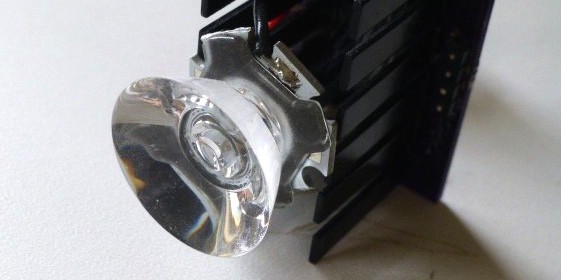
Building on some good work by others (https://publiclab.org/wiki/spectrometer andhttp://myspectral.com/ among others), this spectrophotometer has it’s own bright light (White LED), and uses a lock-in amp and photodiode as a sensitive detector. A Teensy 3.1 is used as the controller and the interface to transfer data to a pc for further analysis. The LED is a high power white one chosen for it’s broad light spectrum. The driver can be programmed (via a resistor) for varying power levels and the unit can be rapidly switched on and off for use with the lock-in amp. A piece from a DVD mounted on a servo motor creates the light spectrum that is moved past a slit, shines on the sample cuvette, and then on the photodiode.

EasyEDA releases a free, online gerber viewer

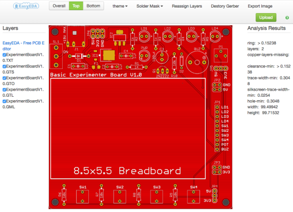
EasyEDA is a free, cloud-based EDA application for drawing circuits, running SPICE simulations, designing PCBs, and even placing orders for fabricating PCBs. Now they have released an online Gerber viewing tool to visualize the Gerber files generated by a PCB CAD tool. The tool supports the Gerber RS-274X format, which is an industry-standard image description format for PCBs. The tool receives the Gerber files in a compressed zipped folder and performs a 2-D rendering to generate high-quality images of top and bottom sides of the PCB. The Gerber viewer also runs a simple design check in the background and displays some useful information about your PCB design, such as its dimensions, minimum clearance, copper trace and silkscreen width, etc.

EasyEDA Gerber Viewer tool user interface

EasyEDA Gerber Viewer tool user interface

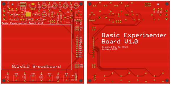
A standalone Gerber viewer like this is a great tool to review the PCB design files before sending them for manufacturing. This tool can be used to verify the component placement and drill holes alignment on the board, as well as to ensure the silkscreen layers are exported correctly in the CAM files. Being on the cloud means it is available to use online at anytime and anywhere, and frees you from having to install any software on your workstation. I am sure this tool will come in handy to the users of EasyEDA for a quick and easy pre-production inspection of their PCB CAD files. At this point, the EasyEDA Gerber Viewer is available at a separate URL. My suggestion to the EasyEDA developer team is to include a link to this tool in the main EasyEDA user interface so that the users can conveniently launch it from there without typing in the URL in a separate browser tab. For a future revision, features like 3-D rendering of PCBs (such as at mayhewlabs) would be cool. The following picture shows the top and bottom images of my basic experimenter board generated using this tool, where I chose Red color for the soldermask. The tool offers 6 other colors for soldermask.

Basic experimenters board top (left) and bottom (right) side PCB views

Basic experimenter board PCB top (left) and bottom (right) side images derived using EasyEDA Gerber Viewer

DIY baby monitor that streams audio over wifi using ESP8266

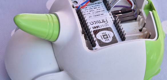
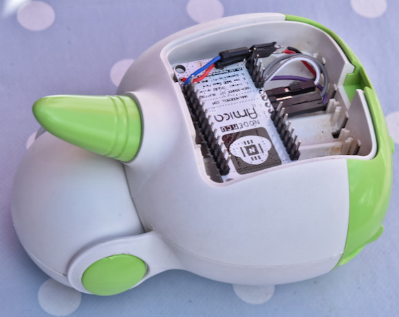
This DIY baby monitor built by Sven337 uses two ESP8266 NodeMCU modules to send audio over wifi. The transmitter part consists of an inexpensive electret microphone to capture the audio in the room. The audio signal is amplified and converted to 12-bit digital samples using Microchip’s MCP3201 SPI ADC chip. The ESP8266 then reads the ADC samples through an SPI interface. The digital sound data is then sent over wifi using UDP packets to the receiving side ESP8266, where the analog audio is reconstructed using an MCP4725 12-bit I2C DAC device followed by an amplifier.

ESP8266 DIY baby monitor

ESP8266 DIY baby monitor

The ADC needs to be audio capable (able to sample at 20kHz or more), cheap, and preferably using SPI (because the ESP8266 has a hardware SPI interface, but no hardware I2C interface). I picked the 12-bit MCP3201, and I am very happy with it. I went for the DIP package, if I had to do it again I would probably buy it in a surface mount package. It’s not usuallymuch harder to solder and occupies less physical space – which in many projects, including this one, can be a real advantage. The MCP3201 is single channel. More channels didn’t cost all that much more, but required more pins, and I couldn’t afford that on the 5×5 cm board the project had to fit on.

[via Hackaday]

Great Cow Basic new release announcement

Great Cow BASIC (GCB) is a BASIC compiler for Microchip and Atmel microcontrollers. It lets you to program in BASIC instead of having to learn assembly or C language and is completely open source! The GCB team has announced the release of Great Cow BASIC v.0.95.007, which has built-in support for Microchip’s latest Xpress Evaluation board and including a host of demonstrations for this board.

The Great Cow Basic development team have published another release that further enhances the Great Cow Basic compiler capabilities. The Great Cow BASIC development team have published another release that further enhances the Great Cow BASIC compiler capabilities.

  • Support for the Xpress Evaluation board including a host of demonstrations for the Xpress Evaluation board.
  • New GCB utility to load hex file into Microchip Xpress board.
  • Improved performance to increase productivity and to reduce compilation time.
  • Improved string handling. Strings can be defined with escape characters like quotes and semi-colons.
  • New volatile bit can be defined that improves setting for specific bits.
  • Enhanced bit Not operator – now works with bit variables!
  • Further improvements to #option explicit.
  • Ethernet support for ENC28J60 adapter with a full TCPIP stack. This is a separate download.
  • Performance improvements to further improve productivity.
  • New optimisation options for A-D.h and PWM.h to reduce the size of generated asm and hex file.
  • Improved support for 900+ Microchip and Atmel 8-bit microcontrollers .

Microchip 10F, 12C, 12F, 16C, 16F, 18C and 18F devices.  The LF devices are now automatically supported (no need for LF specific chip files).

AVR microcontrollers Classic AVR, Tiny AVR and Mega AVR devices.

Support for 16f85xx class of microcontroller plus changes to the supporting hardware files.

New commands to support PPS.  LOCKPPS and UNLOCKPPS.

  • Improved software I2C support that now includes timeout when using software I2C Master.
  • An IDE to make programming as easy as possible including Help and IDE Helpers.
  • 450+ demonstration files that showcase the breadth and depth of capabilities.
  • Support for a large set of supported hardware accessories.

New I2C2 drivers adding 2nd I2C support.

GLCD handling with even more types of GLCD supported.

  • New scalable fonts with added support for extended fonts sets.
  • Increased support for microcontroller timers by supporting all the available microcontroller timers – this can be up to 12 separate timers.
  • New support for HEFM memory.
  • Handling the default Interrupt handlers.
  • Full Linux version of the Great Cow BASIC Compiler and the toolchain
  • New Windows installer for four different type of installation.
  • Plus other new functionality and enhancements or fixes over the previous release – over 190 major changes since the April 2015 release.

Great Cow BASIC an Open Source project.  See http://gcbasic.sourceforge.net/index.php
PIC based IR remote control

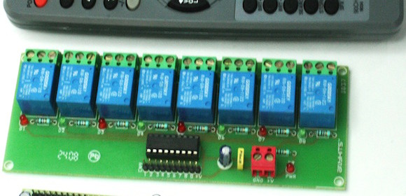
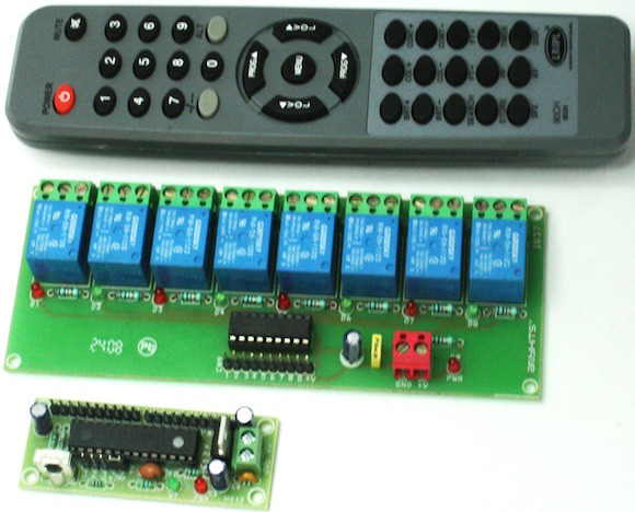
Rajkumar Sharma has shared his design files for single channel and 16 channel IR remote control boards on Electronics Lab. Both of these boards utilize PIC microcontrollers and the TSOP1738 Infra-Red module for receiving the encoded RC5 serial data from a TV remote.

16 Channel IR remote control

16 Channel IR remote control

Features of 16-channel remote control:

  • Supply Remote Transmitter RC5 Philips 2XAAA Battery
  • Supply Receiver 7V to 12V DC
  • Modulation 38Khz
  • Philips RC5 Code Format
  • Operating range up to 20 feet
  • 2 Pin Screw Terminals for Supply Input
  • On Board Power LED
  • Onboard VT (Valid Transmission) LED
  • All Outputs TTL Level provided with Header Connector
  • Jumper (J1) for Mode Selection
  • J1 Open 16 Latch Outputs
  • J1 Closed 8Latch + 8 Momentary


« Older Entries Recent Entries »