Author Archives: R-B

Tutorial 9: ESP8266 and WS2812B RGB LED (or NeoPixel) ring
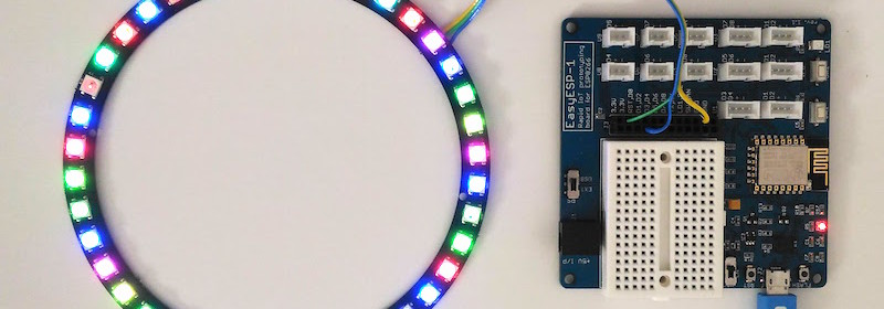
This tutorial describes how to interface a WS2812B RGB LED ring or Adafruit’s NeoPixel ring to ESP8266. The WS2812B is a smart RGB LED with a control circuit integrated in a 5050 SMD package. The RGB data transfer occurs through a single data input line using single NZR communication mode.

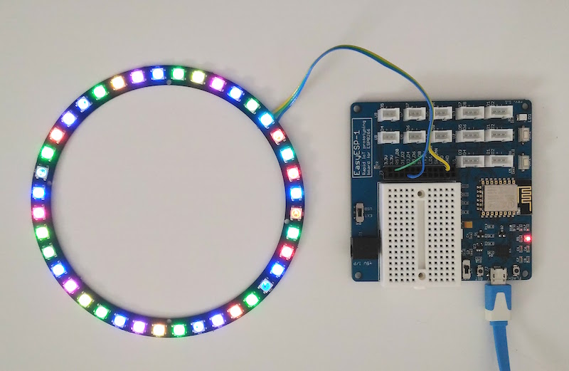
EasyESP-1 driving NeoPixel ring

EasyESP-1 driving NeoPixel ring

Connection between the NeoPixel ring and ESP8266 is through a single data wire. I am using EasyESP-1 here for illustration. The Data In (DI) line of the NeoPixel ring connects to D1 pin of EasyESP-1. VCC and GND pins go to 3.3V and GND terminals of EasyESP-1. I used a 40 RGB LED NeoPixel-compatible LED ring from Elecrow for this experiment.

setup

Wiring RGB LED ring to EasyESP-1

wiring

Power supply and data input pins on the back of Elecrow’s RGB LED ring

For programming the ESP8266 to drive the RGB ring, you will need to install Adafruit’s NeoPixel Library. The library comes with several examples which can be tested with the current setup with a very little modification in the code. Once the library is installed, open RGBWstrandtest example and modify the following two lines as follows:

#define PIN D1
#define NUM_LEDS 40

That’s all you need to change to run this example with the current setup of the EasyESP-1 and RGB LED ring.

Note that you must have your Arduino IDE setup to program ESP8266 according to the instructions posted in Tutorial 1: Setting up the Arduino IDE for EasyESP-1 prior to run this example.

Then upload the modified example code and see the output.

v

RGBWstrandtest output

Buy EasyESP-1 board

More tutorials

EASYESP-1: A RAPID PROTOTYPING AND DEVELOPMENT BOARD FOR ESP8266
TUTORIAL 1: SETTING UP THE ARDUINO IDE FOR EASYESP-1
TUTORIAL 2: EASYESP-1 “HELLO WORLD” EXAMPLE
TUTORIAL 3: CONNECTING AN OLED DISPLAY TO ESP8266
TUTORIAL 4: WORKING WITH ESP8266 WIFI SCAN CLASS
TUTORIAL 5: SETTING UP AN ESP8266 WEB SERVER
TUTORIAL 6: ESP8266 AND BME280 MAKE A LOCAL/REMOTE WEATHER STATION
TUTORIAL 7: ESP8266 AND ILI9341 TFT LCD
TUTORIAL 8: ESP8266 INTERNET CLOCK

Programmable LED dimmer using PIC16F18325

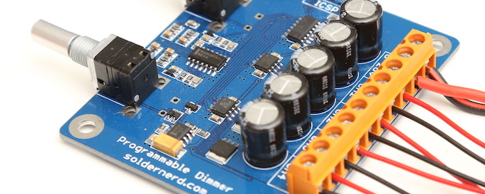
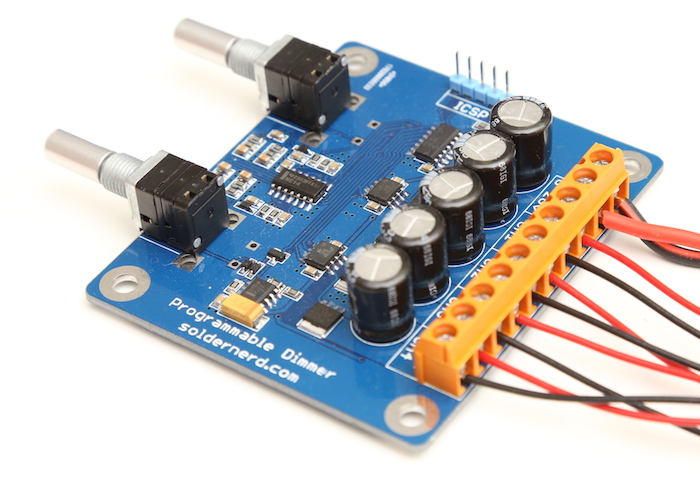
LUKAS FÄSSLER designed a versatile programmable LED dimmer using PIC16F18325 MCU to drive white and RGB LEDs. It operates at a wide range of power supply (6 to 26 volts) and utilizes MOSFET drivers with non-inverting outputs.

Programmable LED dimmer

Programmable LED dimmer

The mosfet drivers are basically the same as before but now with non-inverting outputs: LM5111-1M. There are two of them for a total of 4 outputs compared to only 3 with the previous version.
They now drive much (physically) smaller but no less capable mosfets which allowed me to significantly downsize the whole board to 75x65mm.  The NXP BUK9Y12-40E are rated at 40 volts and offer an on-resistance of 12 milliohms (max @ 25 degrees ) with a 5V drive as we have here. Their large thermal pads a the bottom (NXP calls that package LFPAK) pass heat efficiently to the PCB which then serves as a heat sink. There is also a 30V version that offers even better performance but with a maximum input voltage of 26 volts I thought the 40V version is the safer choice.

Arduino soldering station

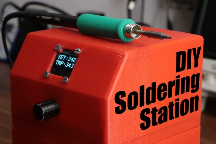
GreatScottLab‘s new project video is about making a DIY soldering station using Arduino and a standard JBC soldering iron. The video also provides all the basic info you would need to know about soldering station, including thermocouples, AC power control and zero point detection.

DIY soldering station

DIY soldering station

Watch the project video below:

Garage parking assistant

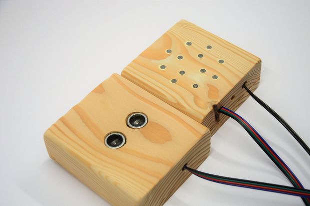
Parking in your home garage could be a bit of challenge if you have a bigger vehicle. You would like to make sure when you parked, you had enough space to walk around the vehicle. This Instructable describes an Arduino based garage parking assistant that would allow you to park in your best spot every time.

Garage parking assistant

Garage parking assistant

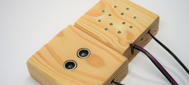
It uses an ultrasonic transducer to measure the distance between your car’s bumper and the backside wall of the garage. A control box with visual indicators using bright Green and Red LEDs signals you when you are on the exact spot. Prior to its first use, you need to calibrate the sensor by parking your car in the best position that you like.

« Older Entries Recent Entries »