Exploring STC 8051 Microcontrollers
|
|
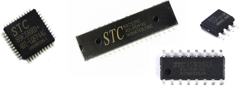
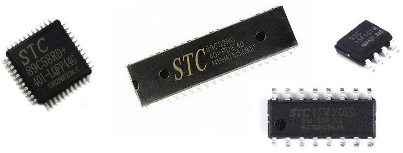
8051 microcontrollers are the first-generation microcontrollers that sparked the modern embedded-system era and established the basic concepts for almost all microcontrollers. In the early 1980s, 8051 microcontrollers were first introduced by Intel. Later other manufacturers like Philips (NXP), Atmel (now Microchip), Silicon Labs, Maxim, etc took the 8051 architecture and introduced their variants of 8051s. Today there are hundreds of such companies which still manufactures this old school legendary micro. of them have even added more features like ADCs, communication peripherals like SPI and I2C, etc that were not originally incepted or integrated. There are even some manufacturers who produce micros under their naming convention/branding while maintaining the basic architecture. Recently I covered an article about Nuvoton N76E003 here. It is based on such ideas. STC (not to be confused with STMicroelectronics) is a Chinese semiconductor manufacturer that operates in the same way as Nuvoton. STC took the model of 8051 just like other manufacturers and upgraded it to new levels by implementing some vital upgrades, enhancements and additions. It also manufactures standard 8051s which are designed to fit in place of any other 8051s from any manufacturer. At present STC has several different variants of 8051s, ranging from standard 40 pin regular DIP 8051s to tiny 8-pin variants. Some are shown below.
STC 8051s vs Other 8051s
STC 8051s, as stated, offers additional hardware peripherals when compared to standard 8051s. There are some STC microcontrollers like STC89C52RC that are same as the standard ones while some others like STC8A8K64S4A12 are more robust with many advanced features. Some key differences between standard 8051s and STC micros are discussed below:
- Packages / Sizes
STC offers microcontrollers in various DIP and SMD IC packages. Thus, instead of using a 40-pin DIP package microcontroller to solve a problem that can be solved with an 8-pin SMD low cost microcontroller, we can avoid using a big microcontroller and thereby save valuable PCB space. Most STC 8051s are, by the way, 100% pin-compatible with other 8051s. This feature makes STC micros easy and viable replacements for devices that use standard 8051s.
- Speed / Operating Frequency
STC microcontrollers are relatively faster than common 8051s as they can operate at higher clock frequencies. For example, AT89S52 has a maximum operating frequency of 33MHz while STC89C52RC can be clocked with an 80MHz source.
- Additional Hardware Peripherals
Some STC microcontrollers have in-built ADC, EEPROM, watchdog timer, external interrupt pins and other peripherals. Some are even equipped with higher storage capacities. These are not available in typical 8051s.
- Operating Voltage
Most 8051 micros need 4.0 – 5.5V DC supply voltage. Some can operate with 3.3V supplies too. Same goes for STC micros. However, there are some STC micros that are designed to operate at yet lower voltage levels. STC offers low power MCUs that operate between 2.0 – 3.6V and general-purpose micros that can operate between 3.6 – 5.5V. The operating voltage ranges and low power consumption figures of STC micros make them well-suited for battery and solar-powered devices.
- Programming Interface
Most 8051s require a parallel port programmer while some require serial port programmer or separate dedicated programmer hardware. STC micros on the other hand can be programmer with a serial port programmer and so there is no need to buy a dedicated programmer. A simple USB-TTL serial converter can be used to load codes into STC micros.
- Other Minor Differences
Other areas of differences include added/reduced functionalities/features. In some STC micros, there additional options for GPIOs, timers, etc while in some other devices these extras are not observed. For example, in STC89C52RC, there is 13-bit timer mode for timers 0 and 1 but this feature is absent in STC15L204EA. Likewise in STC15L204EA, there are many ways for setting up GPIOs which are not present in STC89C52RC.
Documentations and Websites
STC microcontrollers are popular in China and Chinese-speaking countries. Owing to this fact, most of the documentation and even the websites are in Chinese. It is hard to get English documentations. Fortunately, we will not be needing anything else other than device datasheets which are luckily available both in Chinese and English.
Unlike other manufacturers who maintain one website dedicated to their products and themselves, STC maintains several websites. Most are in Chinese. This creates lot of confusion about STC. Some common STC websites are listed below:
Hardware Tools
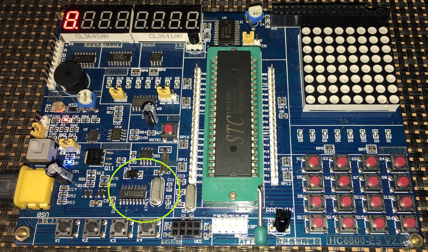
From AliExpress, DX, Alibaba and other similar websites/stores, you can buy any STC development board of your choice. Alternatively, you can buy common STC chips and use them with your existing development board or setup a bread-board arrangement.

One such board is shown above. These boards have lot of hardware devices like external 24 series EEPROM, I2C ADC-DAC, communication and display interfaces, etc already embedded and ready for go. Such boards are, thus easy to use and need less wiring. However, boards as such are relatively expensive and big than the one shown below:
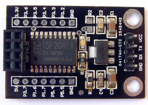
This board is designed to bridge a serial interface between a host micro and a nRF24L01 2.4GHz wireless communication module. However, that doesn’t restrict us from using the STC15F(L)204EA micro embedded in it. If you just want to give STC micros a shot with very little investment then this sort of board is all that you can ever expect.
In my tutorials, I’ll be using both kinds of boards but the main focus will be towards STC15L204EA or similar slightly non-standard 8051s since they are not like playing with typical 8051s.
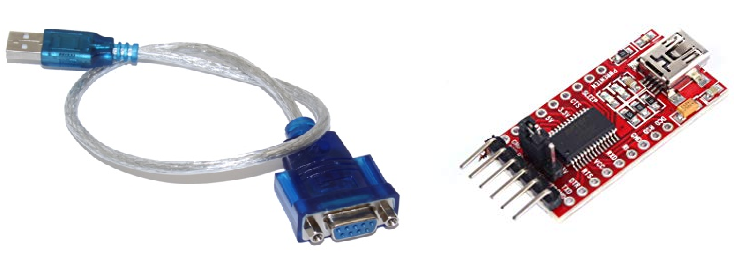
We will also need an USB-serial converter for uploading code.
Apart from these, some regularly used hardware items like LCDs, sensors, wires, etc will be needed. These can easily be found in any starter kit and most are available in any hobbyist’s collection.

Software Tools
Only two software tools will be needed. The first is Keil C51 compiler and second STC ISP tool.
STC ISP tool can be downloaded from here. This is one helluva tool that has many useful features. It a programmer interface, a code generator, serial port monitor, code bank and many other stuffs. It sure does make coding STC micros lot easier than you can possibly imagine.
Keil C51 C compiler will be needed to code STC micros. At present, Keil is the only C compiler that can be used reliably to code STC micros. STC documentations speak of Keil mostly. If you want to use some other compiler like IAR Embedded Workbench, MikroC for 8051, etc other than Keil, your have to add the SFR definitions of your target STC micros and do other stuffs to familiarize it with the STC micro target. Alternatively, you can use models of other similar 8051 model. For example, STC89C52RC is similar to AT89S52. You can use codes for such interchangeably. However, this method won’t work in cases where we have more hardware peripheral than an ordinary 8051 micro. STC15L204EA, for instance, can’t be used like ordinary 8051 or like STC89/90 series micros.
Programming STC Microcontrollers
By default, STC microcontroller database is absent in Keil. It is imperative that this database is added to Keil when using it for STC micros for the very first time. Though this database is not complete in the sense that not chips are enlisted in it, it is still a must or else we will have to use unconventional coding methods by using models of similar microcontrollers of different manufacturers. Personally, I hate unconventional tactics because why use such methods when we can add the database easily. We only have to add this database once.
First run the STC-ISP tool.
![]()
After clicking the STC-ISP tool icon, the application starts and the following window appears:

Don’t worry. It is not an error or garbage text window. It appears so if you don’t have Chinese font database installed in your PC and so just click OK to continue. Recent versions of STC-ISP don’t have this issue.
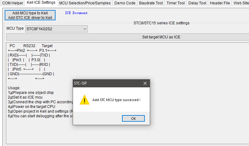
Once the application starts, navigate to Keil ICE Settings tab and locate the highlighted button as shown below:

Now just navigate to Keil installation folder and hit OK as shown below:

Selecting wrong folder will end up with an error and the database won’t be installed.
If the database addition is a success, you’ll get the following message:
Now run Keil C51 compiler.
![]()
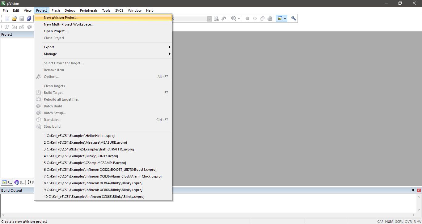
Go to Project >> New µVision Project… as shown below:
Give your project a folder and a name as shown below:

Select STC Database and appropriate chip or similar part number.
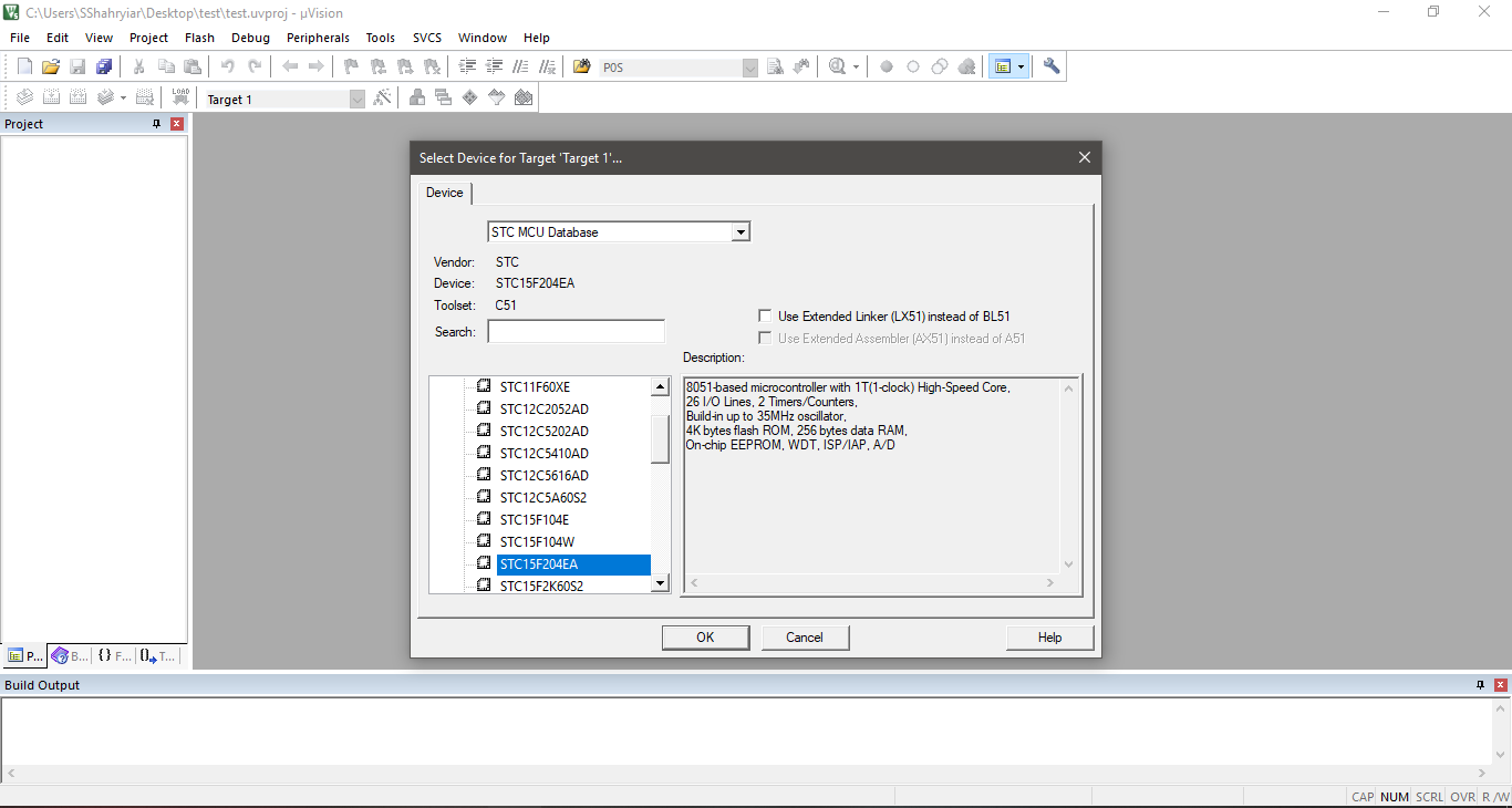
Please note that your target chip may not be in the list. For example, the L-series chips are not enlisted in the database and so they are absent in the list. STC15L204, for example, is not shown in the list. You can use STC15F204EA instead of it as they are similar stuffs. The only difference is their power consumptions. You have to use such tricks when your target chip is not listed. Make sure that the model you selected matches with the target chip or else things may not work properly.
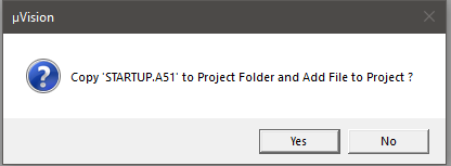
After chip selection, add the startup assembler file to your project.
By default, Keil doesn’t add/create any file and so you’ll see that the project folder has no main source file. We’ll have to create one main source file and add additional files if needed.
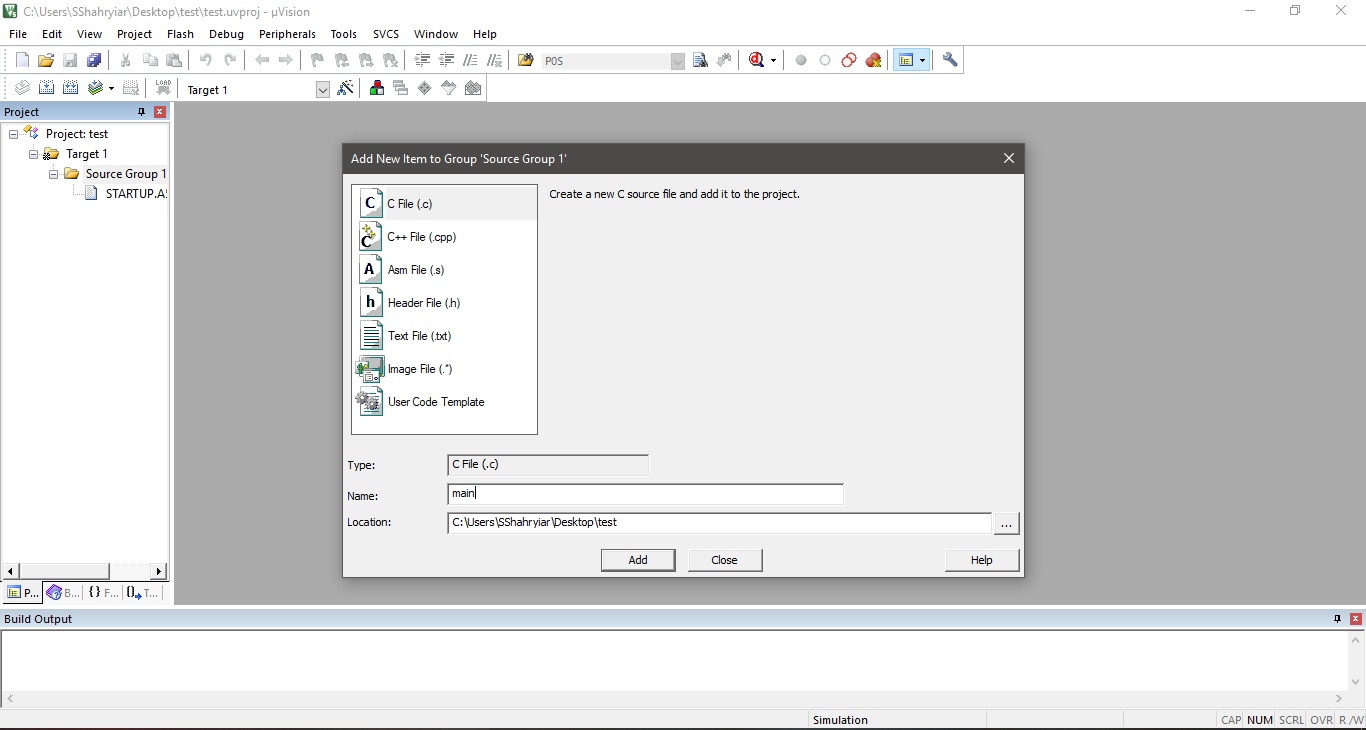
Still we are not ready to start coding. This is because we have not yet added SFR definition header file and other custom optional files.
Again, we need to take the help of STC-ISP tool.
In STC-ISP tool, locate the Header File tab and select appropriate MCU series.
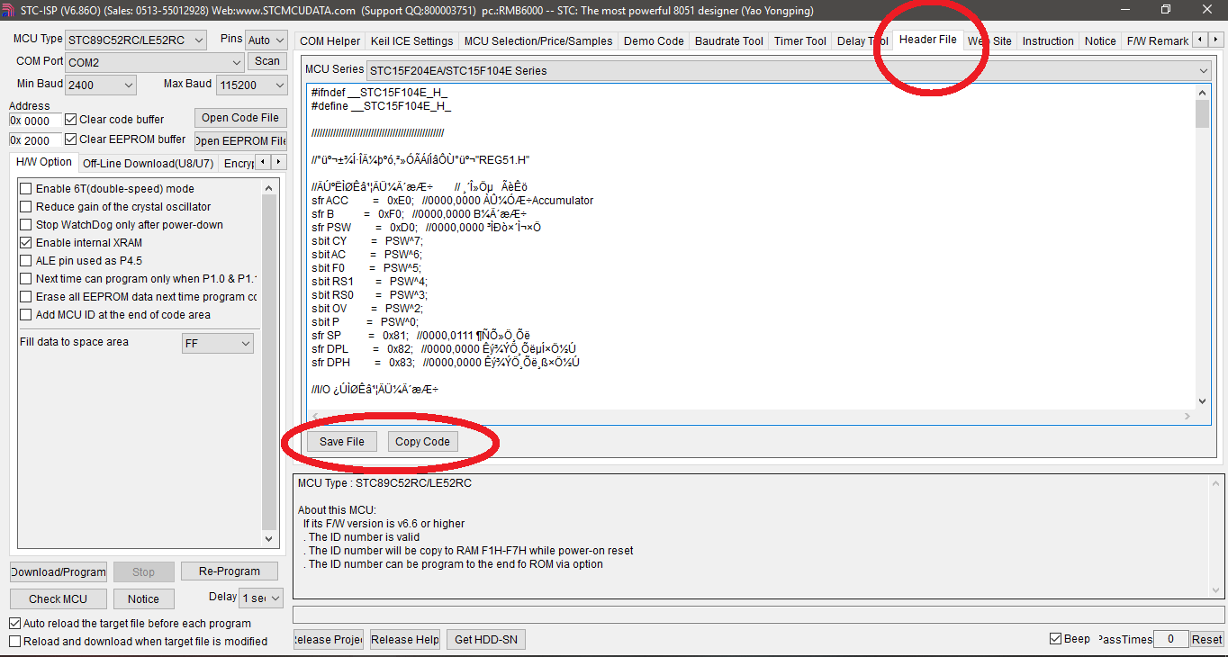
Save or copy the file to your desired location.
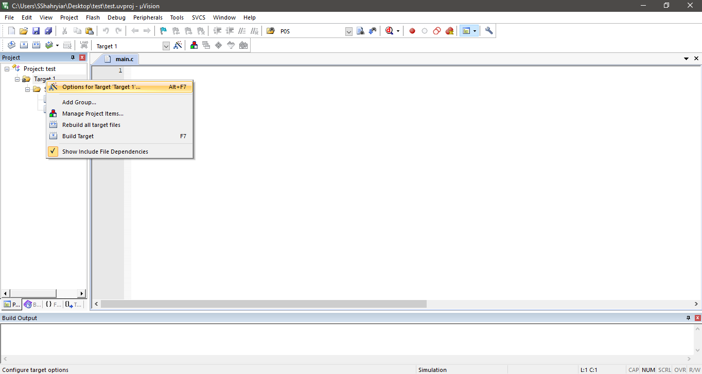
In Keil, go to target options by right click the folder icon and set target options as shown in the following screenshots:
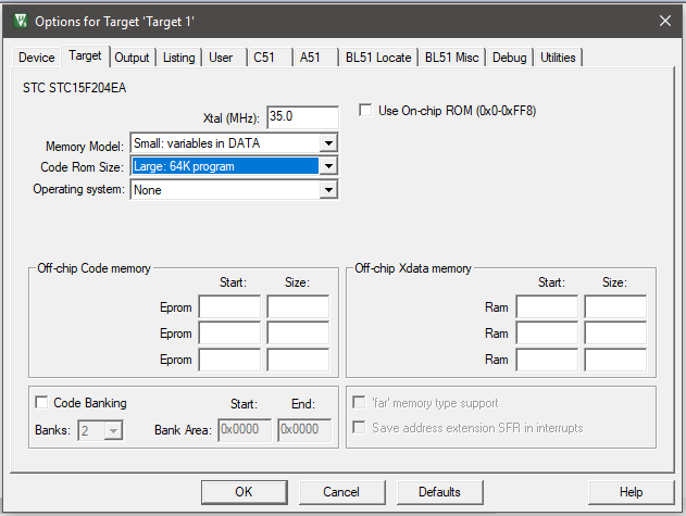
From this window select clock frequency and memory model.
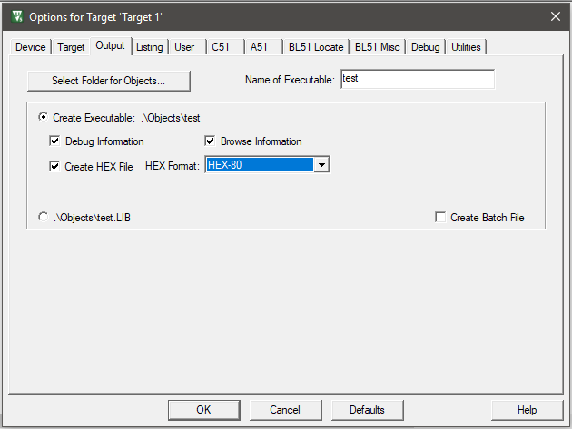
Select Create HEX File from this window as this file will be uploaded in the target chip.
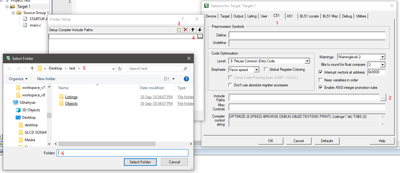
This section above is highly important because here we have to show the compiler the locations of the header or include files. Check the step numbering carefully.

Lastly disable Warning Number 16. Now, we are good to code.
I made a small Youtube video on all the above discussed processes. If you didn’t understand some part or if you are confused at some point, you can watch the video here.
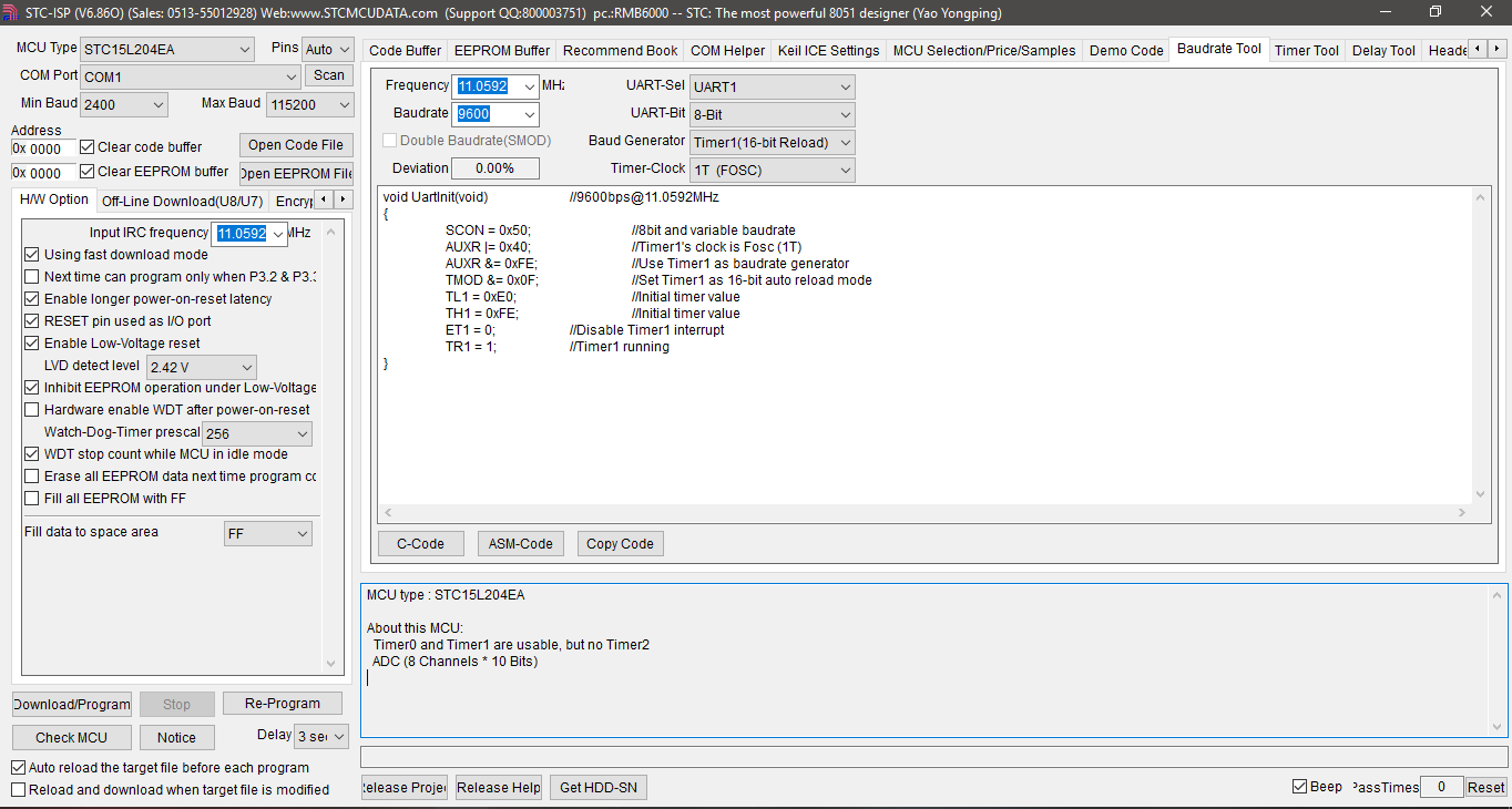
Now let us discuss about uploading codes to STC micros. The most advantageous part is the fact that we don’t need to invest on a dedicated programmer as with other microcontrollers as a simple USB-serial converter will do the job. However, on first go things may look confusing.
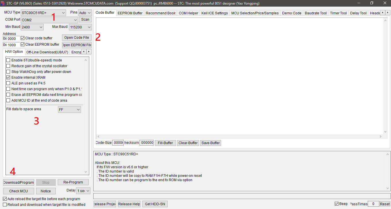
Shown above is the STC-ISP tool’s screenshot with numbers. We have to follow them one-by-one and in incremental order. 1 denotes that we must select the right COM port and part number. You can use Windows Device Manager to find out which COM port is being used for uploading code. Step 2 is to select the target HEX code file. Optionally in step 3, we can set some additional internal MCU parameters. When everything has been set properly, we can hit the Download Program button shown in step 4. If the target microcontroller or board is already powered then the code won’t be uploaded. This is the confusing part because it should have been the other way.
Notice the red arrow in the schematic below. The code is not uploaded by holding and releasing the reset button for some time or by pulling high or low some special pin or by some other means. We need to create a handshake between the PC and the target MCU and this is done when the MCU is powered off and then powered on, i.e. when the micro is powered up.

This is why the red arrow highlights the power switch in the schematic. Though the schematic shows a MAX232-based converter, we can use a USB-serial converter instead.
All of these steps are demoed in this video. Note that no external USB-serial converter/cable can be seen in the video as it is embedded in the board. The following schematic and photo will make this fact clearer. This is why most STC development boards come with such arrangement and without any programmer.

The continuation of this post can be found here.
|
|
Great post! I really enjoyed reading it.
Very nice post. I absolutely love this website. Keep it up!
Wow… this post is excellent.
Wonderful article and very informative. Thank you.
Excellent post, keep sharing…
Really enlightening dive into STC 8051 micros Your comparison of higher clock support, built-in ADCs, EEPROM, flexible voltage, and simple USB-TTL programming versus classic 8051s is incredibly practical and hardware-savvy Thanks for this deep, accessible breakdown
Very nice blog. Thanks
STC microcontrollers are a perfect example of how legacy architectures like the 8051 can be supercharged with modern features—an embodiment of Digital Dopamine for embedded system enthusiasts. The ease of programming via simple USB-serial interfaces delivers instant gratification, fueling the maker mindset with every successful flash.
good
Of course you are supposed write your own code. First try to find the schematic or the manual of the board from online resources. I’m sure you will find something that will match your board. You can also use the labels on the PCB to decode the schematic. ST89C52 is same as AT89S52 or any other similar 8052 microcontroller. You can download the STC ISP tool which comes with code examples and lot of other important stuff. Thanks.
Pretty nice post. I just stumbled upon your weblog and wished to say that I’ve truly enjoyed browsing your blog posts. In any case I will be subscribing to your feed and I hope you write again very soon!
HOW CAN I GET THE ORIGINAL HEX CODE OF THE CHIP STC15F104W
HOW CAN I GET THE ORIGINAL HEX CODE OF THE CHIP STC15W204S
Hey, this tool read and write this device stc90c58rd+, 52rd+,54rd+
Please help
I want to read 90c58rd+ lqfp44 pin mcu this tool worked?
HOW CAN I GET THE ORIGINAL HEX CODE OF THE CHIP STC15W204S
hi sir,
I’m also try to get the hex file from STC15W , kindly help me, and say how to read the hex file from STC15W204S and STC15F104W. I’m very eagerly wait for your response.
Thanks.
I have been also using the 8051 microcontrollers for many years, it is a good one.
Hello,
The Keil C51 device database already comes with devices (see http://www.keil.com/dd ) but the STC parts are not in that database.
To get the STC device database into Keil:
1) Install the Keil C51 tools, from http://www.keil.com/demo
2) Install the STC-ISP tools
3) follow the steps in “Programming STC Microcontrollers”…
To use the STC database in a Keil project, it is actually 2 steps. When this guide says “”Select STC Database and appropriate chip or similar part number” they mean…
1) On the Device tab, on the top, left, change from “device database” to “STC MCU Database”
2) If “STC MCU database” is not in the pull down menu, please re-add the database as described above.
3) After choosing “STC MCU Database” in the “search” box, type the name of your part – the list below filters
4) Click on the device in the list and click “OK.
Hi
I have got a STC11F32xe and I need read EEprom of this MCU.
Can You help Me and say how can I read it?
Hi Mr. Shawon,
Have you ever had this kind problem with STC MCU? (STC8F1K08S2, I also tried with STC15F104W, weird problems)
I tried some below codes with SDCC and it has never worked so far even the compile without error, I tried many options in SDCC – we only the problem with Timer2 (Timer0 and Timer1 work fine), it’s very simple program, just use Timer2 OVF to toggle a LED at P33.
I tried to compile the same code in Keil and it works !
=========== SDCC compile option / Windows =============
-mmcs51 –iram-size 1024 –xram-size 0 –code-size 8192 -DFREQ_SYS=24000000 –no-xinit-opt –nooverlay –noinvariant –noinduction -V –std-sdcc99
===================================
#include //to utilize SFR macro only, nothing special here
SFR(T2L,0xd7);
SFR(T2H,0xd6);
SFR(AUXR,0x8e);
SFR(IE2,0xaf);
SFR(AUXINTIF,0xef);
SBIT(P33, 0xb0,3);
//SBIT(EA, 0xa8, 7);
SFR(IE, 0xa8);
#define ET2 0x04
#define T2IF 0x01
/* Keil
sfr T2L = 0xd7;
sfr T2H = 0xd6;
sfr AUXR = 0x8e;
sfr IE2 = 0xaf;
#define ET2 0x04
sfr AUXINTIF = 0xef;
#define T2IF 0x01
sbit P33 = P3^3;
*/
void TM2_Isr() __interrupt 12
{
P33 = !P33; // Toggle LED at P33
AUXINTIF &= ~T2IF;
}
void main()
{
T2L = 0x66;
T2H = 0xfc;
AUXR = 0x10;
IE2 = ET2;
IE|=(1<<7); //EA =1
while (1);
}
=========================
Do you think that SDCC generated wrong interrupt table or wrong codes for STC MCU? Or what cause the problem?
I also tried the blinky problem on STC15F104W demo board, same problem. The same codes works in Keil but doesn't work in SDCC, I investigate .asm being generated by SDCC and found it's fine, have no idea what happened. I get some STC8G here and will give it a try.
I am for days trying invain to get my STC8A8K64 MCU programmed connected to an USB to serial TTL kabel interface with the sTC-ICP program. Never it works seeing the MCU. I noticed that some people use a diode and a resistor in the RXD and/or TXD communication wires.
And nowhere I see it explained and I’m giving up on using this program and its processors. I never had so much trouble in getting something so simple to work! Even a second new MCU I bought was tested invain. Nothing works!! HELP!!
Can you show me your target MCU board?
I also had this problem and finally I found that my USB to Serial adapter from RobotDyn (using the CH340G chip) had wrong pin indicators. It was transmitting at RX and receiving at TX. After crossing these two pins it worked fine.
We have requirement of Programmer for STC 15F2K32S2 28I LQFP32G IC.
It is an amazing article and I am impressed with your work. Thanks for sharing this to us.
Hi, I have one procesor STC89C52 with internal program (inside in this procesor) and I need transfer this program to new empty procesors. Do you help me? Is this possible copy inside program from one procesor to new (empty) procesor? All the procesors are not RC. Very thanks for your reply (I have absolutely not experience with this).
Possible unless it locked…. I suggest that code transfer be done among same MCUs….
Pingback: Reverse engineering a LED strip RF remote controller – ydiaeresis
hi can you please provide a pdf document of this tutorial thanks
full pdf is not yet published…. after trials, experiments and completion of this tutorial it will be available….
I’m excited to uncover this page. I need to to thank you for ones time for this particularly fantastic read !! I definitely really liked every part of it and i also have you saved to fav to look at new information in your site
I like this article because it provides relevant information for us and I want to be keep updated with you for more posts.
Will be posting a new tutorial post on this micro family soon….
I have Keil Uvision 5 evaluation thingy. (not full for I am a student working around with all of this mayhem development). STC is cheap yeah right. But it is a pain in the ass of some sorth since it has no dedicated compiler. We know it is like the c51 architecture, but then still Keil do not have full support with it.
I followed your instruction on “ADD MCU to KEIL thing blah blah” But failed. and I am getting frustrated. I am working on the STC11L08XE normally found on the ASR V3 module with LD3320 chip, thus without any means of accessing Keil with STC MCU database. Dead end..nothing. head scratching.
Hi
Try to use another compiler such as SDCC. Look at http://sdcc.sourceforge.net/.
It is for free to use.
i just loved your tutorial – “Starting STM8 Microcontrollers- Multiple seven segment display using TIM4 interrupt”. i followed your tutorial and learnt a lot on STM8S in a very short time.
very nice tutorial. Thank you so much for your efforts.
Now i am working on STC 8051s specifically STC15W series with 10 bit ADC for 3 digit seven segment display Voltmeter.
have you made similar tutorials for STCs like you had done for STM8s ?
can you help me on this please ?
Thanks for you appraisal…. Working on STC tutorial…. However the next upcoming tutorial will be on MSP430F5529LP Launchpad….
Thank U very much for this tutorial I would love to invest in this microcontroller coz they are extremely cheap, also I see them in most chinese products please make more tutorials with examples to interface lcds and others thank u
Glad you liked it…. You are most welcome….
Yeah, I’m making tutorial on STC8051s but as of now I’m working on a tutorial on MSP430F5529 Launchpad….
Nice tutoriel, nice video ❤️
Please help. I have a syncmos MCU (sm8954a) witch is a 8051 family microcontroller, it support uart communication but I haven’t syncmos software witch can upload code to microcontroller 😥😥😢
Please help me 🙏🏿🙏🏿
SM8954a