High-voltage seven segment LED display driver with SPI interface
|
|
Seven segment LED displays are known to be resource and power hungry. But because they are visually so charming and readable from a far viewing distance and at a much wider viewing angle as compared to any other electronic displays, they are still hugely popular. The required number of I/O pins to drive the LED segments can be reduced significantly by using an additional dedicated hardware. For example, the MAXIM’s MAX7219 device allows you to interface 8 pieces of seven segment LED modules using only 3 I/O pins of Arduino or any other microcontroller. You can find details on the use of MAX7219 to drive seven segment LED displays in my previous projects 4-digit serial seven segment LED display (SPI7SEGDISP4.40-1R), 8-digit serial seven segment LED display (SPI7SEGDISP8.56-1R), and double-row 4-digit seven segment LED display (SPI7SEGDISP8.56-2R). Since MAX7219 operates at 5V, its output can drive LED segments with forward voltage less than 5V. I have successfully used MAX7219 IC with 1.5″ seven segment LED modules that carry two regular LEDs in series per segment. Inside larger seven segment LED modules, the display segments are made of multiple LEDs connected in series and parallel to provide sufficient light to illuminate the segment, and as such they require a higher forward voltage and more current to operate. Recently, I have designed this display driver board that can be used as a bridge in between larger seven segment LED displays (with segment forward voltage up to 24V) and a 5V microcontroller. On its input side is MAX7219 which receives the display data from the host microcontroller through a 3-wire SPI bus.

Serial driver for large seven segment LED displays
Theory
This project uses the MAX7219 device on the input side to receive the display data from a host microcontroller through an SPI interface. The MAX7219 outputs cannot drive LED segments with forward-voltage above 5V. Therefore, an additional circuit is required to translate the TTL output levels of MAX7219 into appropriate high voltage signals required to operate the large seven segment LED modules. To illustrate I am using eight 5″ displays which require about 14V to drive segments ‘a’ through ‘g’ (each consists of two rows of 7 standard LEDs), and 6V to drive the DP segment (consists of 3 LEDs). The following figure shows the arrangement of multiple LEDs inside the display segments of the 5″ seven segment module I am using.

Arrangement of LEDs inside the 5″ seven segment display
The goal of this project is to design a board that provides
- a TTL SPI interface of MAX7219 to input display data
- outputs functionally compatible with MAX7219 outputs but with an enhanced capability to drive high-voltage (HV) LED display modules (up to 24V)
- a regulated +5V for TTL logic chips and a variable HV source on-board for the LED modules.
Block diagram
The following block diagram explains the overall functionality of the board. The power supply unit provides a regulated +5V to power the logic chips, and a variable high voltage (HV) required to drive the LED segments. The value of HV can be adjusted as needed through a potentiometer. On the input side is MAX7219 chip which receives display data from a host microcontroller through a serial interface. In order to find more detail about the MAX7219 interface, visit MAX7219 based seven segment LED display. The output segment driver pins of MAX7219 are translated to high voltage signal lines using UDN2981A, which is a 8-channel source driver. In order to prevent the DIG0-DIG7 sink outputs of MAX7219 from any possible damage (or malfunctioning) due to high voltage signals applied to LED segments, external sink lines are created using ULN2803. Since the DIG0-DIG7 lines of MAX7219 are active low and ULN2803 inputs are active high, an eight channel logic inverter (74HC540) is used in between to make the two sets of signal lines compatible. Imagine a situation when outputs of UDN2981A (which is set by varying HV) is higher than the forward voltage of LED segments by more than 5V. If DIG0-DIG7 sinks are used directly without the arrangement discussed above, then no matter what is the output state of DIG0-DIG7, the LED segments will always be on. So the use of 74HC540 and ULN2803 as external sinks prevents this malfunctioning.
Note: Remember that the maximum sink current allowed by ULN2803 is 500mA per channel, which means the sum of individual segment current per digit should not exceed this value.

Block diagram of HV seven segment LED driver
Circuit diagram
Following circuit diagrams are designed to fulfill the functional requirements of the block diagram discussed above. The power supply unit uses LM317 to derive an adjustable HV power supply. According to the datasheet, LM317 output is adjustable over 1.2-37V. Obviously, the input must be higher than 37V to achieve that range of output. However, I recommend to limit the application of this board to 24V max for HV, which is enough for almost every known LED size. The largest seven segment LED display I have known is of 12″ size, which has 4 rows of 10 LEDs in series per segment, and so the required forward voltage is approximately 20V. The output of LM317 also goes to the input of LM7805 to generate a regulated +5V power supply. The following circuit diagram shows the details of the power supply unit. The value of HV is adjusted through a potentiometer (POT1 = 5K). The value of R1 is 240Ω. The formula for HV is,
HV = 1.25(1+POT1/R1)
C1 and C4 are 50V rated ceramic capacitors, whereas C2, C3, and C5 are electrolytic.

Power supply circuit (Click to enlarge)
The schematic of MAX7219 and voltage translation unit is shown below. R2 through R9 are current limiting resistors for LED segments a–g and dp. I am using 39Ω for segments a through g, and 540Ω for dp. Knowing the forward voltage and current required for each segment, you can now set the value of HV accordingly. Suppose we want 40 milliamps for each of the seven LED segments which have forward voltage of 14V. With 40 milliamps current the potential drop across 39? resistance is 1.56V. So it is good to set HV to 14+1.56≈16V. With 16V output, the current through dp segment (Vf = 6V) would be (16-6)/540 ≈ 19 milliamps.

Driver circuit (click to enlarge)
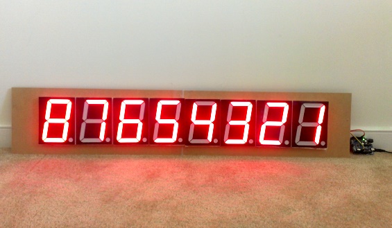
I have designed a printed circuit board of the above design. Here’s a picture of a finished HV seven segment LED driver board. It is 10cm x 10cm in dimensions and provides an approximately 8cm X 4cm (3.2″ X 1.5″) size double-sided universal prototyping area for experimenting. The DC input is given through a 2-pin terminal block.

Fully assembled board
Buy a PCB for this board

Closer look of interface pins
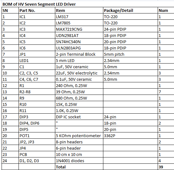
Complete list of parts needed to assemble the board
Application
This board can drive up to 8 common cathode seven segment displays. Wiring the displays to the board is easy. Segments a–g, and dp of all the displays should connect to header JP2, whereas their common cathodes will go to the header pins D0-D7 of JP3. Serial data is fed through JP4. Header JP5 provides access to DOUT pin of MAX7219, which allows cascading of multiple boards. I am powering the board with a 24V DC wall-wart, and the HV output of LM317 is set to approximately 16V. I have tested it with an Arduino board using the LedControl library and it works like a charm.

Eight 5″ CC LED displays arranged in a row

Back side view

Arduino sends data the display board
Displaying 1 through 8 using LedControl library
I also tested my digital light meter project successfully with the big display board. The beauty of this design is it is functionally same as using MAX7219 and so you don’t have to make any changes to your code.

Running Light Meter project
Summary
The HV seven segment LED driver board is designed to simplify the interface of bigger seven segment display modules to microcontrollers. The board receives data serially through an SPI interface using MAX7219 device at the input side. The outputs of MAX7219 are enhanced using external circuits to provide high voltage multiplexed control signals to drive bigger size seven segment LED display modules. The board also features an adjustable high voltage source for the displays, a regulated +5V output, and a prototyping area for experimenting.
Can I buy this board?
I am selling PCB of this board for $8.99 on Tindie. If you are interested, visit the link below:
Buy HV Seven Segment LED driver board PCB for $8.99.
It can also be purchased from our Elecrow Store with worldwide shipping.
Buy PCB Only for this Display Driver
|
|
Hi, I am from India, and here the buy option not available from the site you specified. If you can send the gerber file then it will be of great help
Thank you
Hi,
Great project, I have a question:
I like to use 12V 5050SMD strip to create the segments. Each individual segment with 3 led consume 56mA at 12Volt. What is the max numbers of 5050 smd led that I can use for each segments and how I can connects it (serial/parallel mode)? I have difficult to calculate the max currents that the circuit are able to supply. Thanks for the information.
Hi R-B I’m in need of some help.
I thought this would be the answer to my building some 10″ digits for my cricket club’s scoreboard so I bought 2 of these.
I’m using a 24V P/S to power digits with 21 LEDs per segment as 3 strings of 7 LEDs with a 330 Ohm resister in series with each string of 7.
When I power them directly with the 24V supply they’re the brightness I’d expect.
Unfortunately I’ve hit a couple of snags with both of the boards.
1. I’m only getting *0.41V* across the LEDs — so they’re REALLY dim 🙁
2. I’m only getting 21.9V as HV – which would be fine apart from (1). Even at 22V the LEDs should have significantly more than 0.41V through them.
According to the formula you’ve used above I should be able to drive up to 27V:
The value of R1 is 240R. The formula for HV is, HV = 1.25(1+POT1/R1)
i.e. For POT1 = 5k and R1 = 240R HV = 27.3V
3. One of the boards is no longer working. Test points for +5V/HV all ok, but nothing driving the segments.
Any chance of a Gerber file — happy to contribute of course — just that the season’s started and I’m struggling 🙁
I can control the INTENSITY of the MAX7219 to make it even dimmer so I can’t think it’s that and TEST MODE shows same dimness 🙁
What do you think I have done wrong? Is there anything I can test?
I’d really like any advice, words of wisdom/insight you may have.
Great project. Congratulations. Unfortunatly the postal cost is more then the cost of the board.
hello..
can i tell me alternative IC for UDN2981.
Hi,
the drivers are out of stock. Any idea when they are available?
Best regards
Werner
They r available now.
Hi guy i dispose to a comone anode 7 segment display, please can i get the modfication for your driver board.
thank you in advance.
Hi,
I would like to use your driver board for a project in the school i work, so i tryed to buy your driver board, but tindie told me there’s no shipment to Mexico, is there any way to enable the shipment to Mexico, or could i buy you the gerber files?
Thanks for sharing what you did, you do a great job!!
Email me at rajbex at gmail.com and I will send u the gerbers.
thanks for the help i need gerber file
Anyway: many thanks for sharing your knowledge with us ! Real good stuff !
Hi, how could this board be modified for usage with common anode 7segment …
Hi Remi. I would like to try the board driving left and right timer displays but the website doesn’t ship to my country. Can you please reply about how I can get a copy of the board layout to produce the board locally here in Australia. Thanks
Hi — this project perfectly suits my needs and thanks for designing it. Just bought your board and I’ve assembled it, but was curious where I test the forward voltage coming from the pot.
Ok, never mind. I just realized it was on the breakout pins. You’ve thought of everything!
hi, i you know, where i can buy 7 segment display spi control (20 -30 cm more less)
many thanks
Hi, I’m interested in using your drive board in one of my projects, but the website store doesn’t send the board to Brazil, I would like to buy the layout directly from you, so I can print the circuit board localy, do you think this is possible? Send me an email .
Thank you!
Hi, I’m interested in using your drive board in one of my projects, but the website store doesn’t send the board to Romania, I would like to buy the layout directly from you, so I can print the circuit board localy, do you think this is possible? Send me an email and we talk
Just sent you the gerber files in your email.
Why do people always make these type of things sell them and never help out!!!!!
Just about every project the author never posts a comment to help others.
Low blow!!!!
I am using a max7221 for common anodeLEDs wondering how to modify your set up to use this chip…also did you hear back from Ismail on his idea…?
Pingback: 8 x 8 Laser Matrix for Fun – Part I | Technoshaman's Experiences
Hi R-B,
We can directly driver RED or Green for sink side. Just Use UDN2981 and Connect Sink side directly to MAX7219 for upto 4 Display maximum. MAX7219 Sink is 500mA. I have tried and it just work perfect 🙂
Just an idea…. if someone might be interested…!
Hi. This will be a great help for our project regarding synchronized digital clock. Can you tell me where can i simulate this project? Thank you 😀
this is cool i am also trying to build the large seven segment display my logic and my circuit completely working fine and displaying number is also good but my problem is some of the segments not completely off while displaying(5digit) number
can you give me suggestions
thank you
I’ve the same problem with ULN2003 and 74LS04 inverters, when the segment A digit 0 is on also the same segment on the others digit is slightly on. I can’t find a way to resolve this problem.
Same problem here. Some segments are slightly on.
Any suggestion?
Thank you.
Solved with pull-down resistors in the MIC2981 (UDN2981A) inputs.
Thanks.
I tried 10K pull-downs on the UDN2981A inputs, but it did not solve the issue with segments slightly on for me. What value have other people used?
I also found that I needed to change the 500 ohm pot to 5K to get the range I needed on the HV.
Great project. Congratulations.
But I’ve the same problem, some of the segments not completely off.
10K pull-downs on the UDN2981A inputs did not solve the issue.
Has anyone found a solution?
Hi R-B,
I’ve noticed that the UDN2981A-T is not being produced anymore and therefore not vailable at most suppliers.
What could be a good alternative for it?
MIC2981
Hi R-B,
I have a Question. Can i use MAX7219 Brightness control feature by using UDN2981A to drive large displays ? I mean to ask does max7219 output is PWM ? will the same driving UDN2981A PWM on pins ? so i can change the bright ness of the large displays ?
Thanks.
Hi, I trying to understand how i could modify this to work on common anode. Would replacing the max7219 by a ICM7218a work?
Just purchased couple of these boards, could you tell me if this circuit has flickering or any other problems with it. I am thinking of building a scoreboard with this circuit so before I do all the assembly any experience problem from you would be helpful.
No I haven’t noticed any flickering or any other problems with this circuit.
I think this is not the best solution. TPIC6B595 is far better.
Hi Alex,
Can you suggest how would you configure TPIC6B595 for driving 8 digits? How many TPIC6B595 devices would you need?
Pingback: Belgaum news | About Belgaum | Belgaum information | Belgaum district | Belgaum city | Belgaum Hotels | Belgaum People | Belgaum tourism | Belgaum entertainment | Belgaum students | Inside facebook | Hack | make use of | technical news | | Controlling Hig
Why did you use a buffer between the max7219 and the uln2803 ? i am also looking into making a driver for big 7 seven segment displays and i found this http://dorkbotpdx.org/blog/paul/big_7segment_countdown_timer which looks ideal but has a high count part list per display, i also found an shift register which has an open drain output http://www.nxp.com/documents/data_sheet/NPIC6C595_Q100.pdf since im thinking of using common anode display the second option looks better
where did you buy the 5″ display ?Anyway nice project
Hi
well done ,good design But
As per my knowledge This design is not cost effective .I can design same thing by using low cost IC and we can attach somany display serialy one by one and there is no flickering will occure and it can maintain persistence of vision also.
Can you tell us more about your idea? We would love to hear that. Thanks.
Sir, I dnt use UDN IC, I can amplify it using mosfet can i?