Lab 4: Interfacing a character LCD
|
|
Description
HD44780 based LCD displays are very popular among hobbyists because they are cheap and they can display characters. Besides they are very easy to interface with microcontrollers and most of the present day high-level compilers have in-built library routines for them. Today, we will see how to interface an HD44780 based character LCD to a PIC16F688 microcontroller. The interface requires 6 I/O lines of the PIC16F688 microcontroller: 4 data lines and 2 control lines. A blinking test message, “Welcome to Embedded-Lab.com”, will be displayed on the LCD screen.
Required Theory
All HD44780 based character LCD displays are connected through 14 pins: 8 data pins (D0-D7), 3 control pins (RS, E, R/W), and three power lines (Vdd, Vss, Vee). Some LCDs have LED backlight feature that helps to read the data on the display during low illumination conditions. So they have two additional connections (LED+ and LED-), making altogether 16 pin. A 16-pin LCD module with its pin diagraam is shown below.

Control pins
The control pin RS determines if the data transfer between the LCD module and an external microcontroller are actual character data or command/status. When the microcontroller needs to send commands to LCD or to read the LCD status, it must be pulled low. Similarly, this must be pulled high if character data is to be sent to and from the LCD module.
The direction of data transfer is controlled by the R/W pin. If it is pulled Low, the commands or character data is written to the LCD module. And, when it is pulled high, the character data or status information from the LCD registers is read. Here, we will use one way data transfer, i.e., from microcontroller to LCD module, so the R/W pin will be grounded permanently.
The enable pin (E) initiates the actual data transfer. When writing to the LCD display, the data is transferred only on the high to low transition of the E pin.
Power supply pins
Although most of the LCD module data sheets recommend +5V d.c. supply for operation, some LCDs may work well for a wider range (3.0 to 5.5 V). The Vdd pin should be connected to the positive power supply and Vss to ground. Pin 3 is Vee, which is used to adjust the contrast of the display. In most of the cases, this pin is connected to a voltage between 0 and 2V by using a preset potentiometer.
Data pins
Pins 7 to 14 are data lines (D0-D7). Data transfer to and from the display can be achieved either in 8-bit or 4-bit mode. The 8-bit mode uses all eight data lines to transfer a byte, whereas, in a 4-bit mode, a byte is transferred as two 4-bit nibbles. In the later case, only the upper 4 data lines (D4-D7) are used. This technique is beneficial as this saves 4 input/output pins of microcontroller. We will use the 4-bit mode.
For further details on LCDs, I recommend to read these two articles first from Everyday Practical Electronics magazine : How to use intelligent LCDs Part 1, and Part 2.
Circuit Diagram
Data transfer between the MCU and the LCD module will occur in the 4-bit mode. The R/W pin (5) of the LCD module is permanently grounded as there won’t be any data read from the LCD module. RC0-RC3 serves the 4-bit data lines (D4-D7, pins 11-14) of the LCD module. Control lines, RS and E, are connected to RC4 and RC5. Thus, altogether 6 I/O pins of the PIC16F688 microcontrollers are used by the LCD module. The contrast adjustment is done with a 5K potentiometer as shown below. If your LCD module has backlight LED, use a 68? resistance in series with the pin 15 or 16 to limit the current through the LED. The detail of the circuit diagram is shown below.

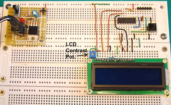
The whole circuit constructed on the breadboard is shown below. If you want to reduce some of the wire connections on the breadboard and save some space, you can first construct my PIC16F688 breadboard module, and then insert it on the breadboard (shown in the following pictures).


LCD interfacing to PIC16F688 Breadboard Module

/*
Lab 4: Blink Character Message on LCD
Internal Clock @ 4MHz, MCLR Enabled, PWRT Enabled, WDT OFF
Copyright @ Rajendra Bhatt
October 9, 2010
*/
// Define LCD module connections.
sbit LCD_RS at RC4_bit;
sbit LCD_EN at RC5_bit;
sbit LCD_D4 at RC0_bit;
sbit LCD_D5 at RC1_bit;
sbit LCD_D6 at RC2_bit;
sbit LCD_D7 at RC3_bit;
sbit LCD_RS_Direction at TRISC4_bit;
sbit LCD_EN_Direction at TRISC5_bit;
sbit LCD_D4_Direction at TRISC0_bit;
sbit LCD_D5_Direction at TRISC1_bit;
sbit LCD_D6_Direction at TRISC2_bit;
sbit LCD_D7_Direction at TRISC3_bit;
// End LCD module connection definition
// Define Messages
char message1[] = "Welcome to";
char message2[] = "Embedded-Lab.com";
void main() {
ANSEL = 0b00000000; //All I/O pins are configured as digital
CMCON0 = 0x07 ; // Disbale comparators
TRISC = 0b00000000; // PORTC All Outputs
TRISA = 0b00000000; // PORTA All Outputs, Except RA3
Lcd_Init(); // Initialize LCD
do {
Lcd_Cmd(_LCD_CLEAR); // CLEAR display
Lcd_Cmd(_LCD_CURSOR_OFF); // Cursor off
Lcd_Out(1,4,message1); // Write message1 in 1st row
Lcd_Out(2,1,message2); // Write message2 in 2nd row
Delay_ms(1000); // Wait for 1 sec
Lcd_Cmd(_LCD_CLEAR); // Clear display
Delay_ms(1000); // Wait for 1 sec
} while(1); // Infinite Loop
}

|
|
How to convert this display to touch one
How to change this display to touch one
sir, is the coding for 16*2 display same to all other displays ???
sir,
The LCD charcter display project componets list &circuit diagram please send sir , i am design and working for this project in my lab
sir I am using PIC16F677 to program 16*2 LCD display I am able to display in both lines of lcd display but not in parallel manner. please can you tell me how to display in both lines at a time
may be error in this line
CMCON0 = 0x07 ; // Disbale comparators
I like your website very much . . . .Thank you
Great website and great tutorials thank you
I HAVE COPIED THE CODE BUT IT IS SHOWING AS “TOO MANY ARGUMENTS IN A FUNTION” AND WHERE ARE THE FUNCTION FOR LCD INIT, LCD OUT, LCD CMD, PLZ PROVIDE ME WITH THIS DETAILS THANKS
thank you for you website and for the wonderful knowledge
Your website is wonderful…good theory information related to each experiment for the beginner..thanks alot
i am using PIC18f452 with jhd162a LCD at 20 MHz. i am using the same code as mentioned in above article but i am getting only black boxes on first line of the LCD, i have double checked the connection between microcontroller and LCD which are according to the code.what may be the problem plz help…
Great site found by pure chance. Is it possible to have all the tutorials in a downloadable .pdf for they make for very interesting reading. Would make flicking between them easier and they are a great resource for memory jogging.
Kind regards
Bruce
Pingback: Help With My First LM13232AFW GLCD Project
can any one please tell me the commands to display on 2nd, 3rd and, 4th lines of a 16×4 lcd module. i searched it on internet a lot but cant find it 🙁 . please help me.
Pingback: PIC16F8870 & RS232 RFID READER & Mikro C
Generate custom characters and display them on LCD
http://www.lcdinterfacing.info/Custom-HD44780U-characters.php
This webpage describes a simple technique to display characters from both internal character generator and user designed chracters on an LCD. The Hitachi HD44780U or a compatible controller is used here in 8-bit interface mode. The program code given here defines the custom characters and loads it into the character generator RAM (CGRAM).
hy can you help me in a problem ??
do you know how to scroll text on lcd 2×16 ?
scrolling text in the same time on the 2 lines.give an example of microC code.
regards,
gabrielmrc
Muy buen proyecto.
los felicito lo aplicare a mi sesión de aprendizaje con mis alumnos de 5º grado de secundaria.
Ruben Montesinos.
Pingback: Electronics-Lab.com Blog » Blog Archive » Tutorial on interfacing a LCD display to a PIC microcontroller