Netduino Day 5 – Writing to an SD Card

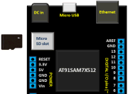
Expandable memory is always a plus no matter whether it’s a Phone, Camera or a Microcontroller. Even advantageous if we know how to use it. In this fifth day Netduino tutorial, we will learn a few writing operations about an SD card. We will learn how to write to a text file, shown as an example of writing a log. The Logger class is also capable of creating a text file at any given location then writing some text information to it.

Read more

Revised version of the PIC12F microcontrollers breakout board

The 12F series of PIC microcontrollers are handy little 8-pin devices designed for small embedded applications that do not require too many I/O resources, and where small size is advantageous. These applications include a wide range of everyday products such as hair dryers, electric toothbrushes, rice cookers, vacuum cleaners, coffee makers, and blenders. Despite their small size, the PIC12F series microcontrollers offer interesting features including wide operating voltage, internal programmable oscillator, 4 channels of 10-bit ADC, on-board EEPROM memory, on-chip voltage reference, multiple communication peripherals (UART, SPI, and I2C), PWM, and more. This is a revised version of the previous

Read more

Netduino Day 4 : Eight Digit Seven Segment LED Display with MAX7219

In Day 3 tutorial, we learnt basics of seven segment LED displays and discussed about a time-division multiplexing technique that reduces the number of required microcontroller I/O pins to drive multiple seven segment LED displays. Today we will move a step further and discuss about a serial interface (SPI) for driving 8 seven segment LED displays. The technique uses MAXIM’s MAX7219 LED driver chip that allows you to control 8 (or more in cascade configuration) common-cathode seven segment LED displays with only 3 I/O pins of Netduino. For illustrative purpose, we will use our 8-digit serial seven segment LED (8DSSSLED) display module here. The benefit

Read more

Understanding Logic Analyzer basics using SCANALOGIC-2 EDU KIT

A logic analyzer is an excellent tool for capturing many digital signals at once and displaying their timing relationships. It is particularly useful in verifying and debugging digital circuits. This tutorial is intended to provide a quick overview of a logic analyzer tool and its uses in analyzing and decoding data flowing on multiple signal lines or bus in a digital system. The logic analyzer tool is extremely helpful in troubleshooting problems arising from timing violations and transients on buses. In this article, I am going to use the SCANALOGIC-2 educational kit from IKALOGIC to illustrate very basic features of

Read more
« Older Entries Recent Entries »