Running LED dice
|
|
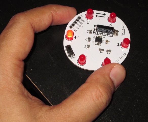
Tons of LED dice projects with different output forms have been published online. The most common output configuration in those projects is a 3-1-3 setup (two rows of three LEDs and one LED at in the middle) of seven LEDs, which simulates the actual patterns of dots found on the six faces of a traditional dice. When it is rolled, one or more LEDs are selectively turned on to display a random number between 1 to 6. This project is about a similar LED dice but with a slightly different output form. It uses 6 LEDs which are arranged in a circular pattern and are labeled 1 through 6. They create a chasing effect when the dice is rolled. The chasing effect slows down gradually, and eventually stops at one of the six LEDs. The rolling is done by a gentle shaking of the dice horizontally. The LED dice is powered with a 3V coin cell battery and uses PIC12LF1822 microcontroller to generate a random number and drive the output LEDs.
Running LED dice
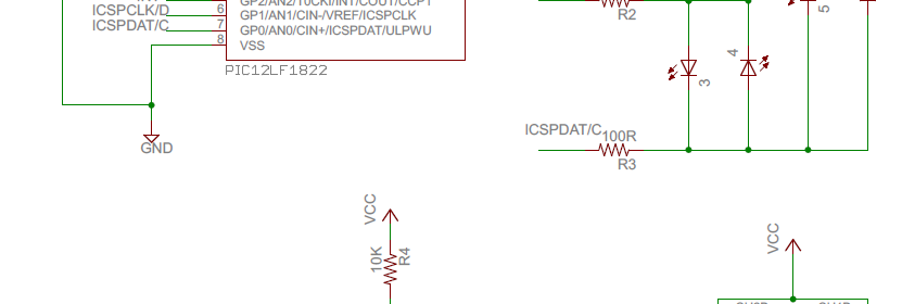
Circuit diagram
The six LEDs are driven through 3 I/O pins of PIC12LF1822 microcontroller using the Charlieplexing technique. Three 100 Ohm resistors are placed in series with the I/O lines to limit the LED currents. A horizontally placed tilt switch (also known as vibration switch) is used to sense the shaking of the dice. A tilt switch is simply a tube with a tiny conductive metal ball that rolls inside it, and has two electrical contacts that are accessible from external leads. When its tilted upright, the ball rolls onto the two metallic contacts, thus short-circuiting them together. The tilt sensor along with a pull up resistor generates an interrupt signal on GP2/INT pin of the PIC12LF1822 microcontroller and the dice is rolled. A power on/off slide switch is also included in the project. In case you forgot to turn it off, the PIC microcontroller will be programmed to automatically go to sleep mode to save the power consumption. A circular shape PCB is designed for this project. The CR2032 battery holder is placed on the bottom side of the PCB, whereas rest of the electronics and LEDs go on the top side. The design files can be downloaded from the link provided at the end of this section.
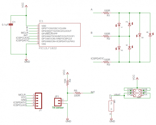
LED dice circuit (click to enlarge)
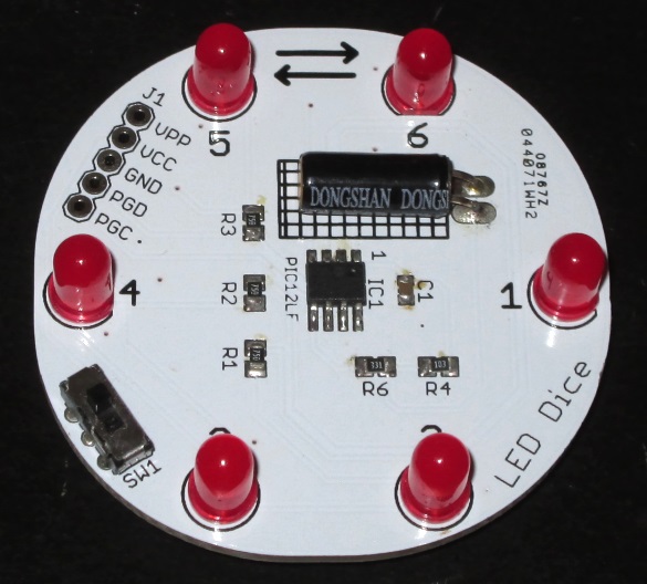
Completed dice top view
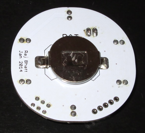
Battery goes to the bottom side of PCB
Download Eagle CAD Design Files
Firmware
The LED dice firmware was developed using mikroC Pro for PIC Compiler. For simplicity, I used the built-in rand() function to generate a pseudo-random number between 1 and 6. The rand() function in mikroC gives a pseudo-random number between 0 and 32767. It is then scaled to between 1 and 6 through a modulus division by 6 (which gives a remainder output between 0 and 5) and adding 1 to the remainder. I ran the same algorithm on a higher end PIC microcontroller (PIC18F44K22 at 16MHz) and recorded the frequency of the dice output for 100000 rolls just to see how the output distribution looks like. The mean value and standard deviation of the distribution were 16667 and 3207 (19% of mean), respectively. In 100000 rolls, number 3 exhibits the highest frequency, while 4 has the least number of occurrence. The distribution of outcome was not very impressive (that’s why it is called pseudo-random), but it should work for this basic dice project. Here is the output for 100000 rolls.
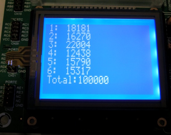
Frequency of dice outputs for 100000 rolls
External Interrupt is enabled on RA2/INT pin. When the dice is rolled (shaken in this case), the tilt switch outputs a pulse signal on this pin and generates a hardware interrupt. The PIC microcontroller then displays a chasing effect with the circular pattern of LEDs, always starting from LED 1. The effect is slowed down gradually and finally stopped at the pseudo-number generated using the rand() function with some additional manipulation. The output LED is programmed to stay on for 2.5 seconds and then the PIC is put to sleep. The PIC wakes up when the dice is rolled again and an interrupt signal is issued on the RA2/INT pin.
// Define Charlieplexing lines
#define Row_A RA4_bit
#define Row_B RA5_bit
#define Row_C RA0_bit

// Define port direction and output states for each LED
const unsigned short TRISA_Data[]= \
               {0xCF, 0xCF, 0xDE, 0xDE, 0xEE, 0xEE};
const unsigned short PORT_Data[] = \
               {0x10, 0x20, 0x20, 0x01, 0x10, 0x01};
unsigned int j, i,k, random_num;

void ALL_LEDs_OFF(){
  PORTA = 0x00;
  TRISA = 0xFF;
}

void LED_ON(unsigned short num){
  TRISA = TRISA_Data[num];
  PORTA = PORT_Data[num];
}

// Interrupt service routine
void interrupt(){
  if(INTCON.INTF == 1) asm nop;
  INTCON.INTF = 0;
}

void main() {
 ANSELA = 0b00000000;  // Disable analog inputs
 TRISA  = 0b00001000;  // RA3 is input only
 PORTA = 0;
 OSCCON = 0b01101000;  // Set internal clock to 4MHz
 INTCON = 0b10010000;  // Enable external hardware interrupt
 OPTION_REG.INTEDG = 0; // External interrupt on falling edge of RA2/INT pin
 Delay_ms(100);

do {
  random_num = rand()%6 ;
  for (j=0; j<=random_num+36; j++){
      i = j%6;
      LED_ON(i);
      for (k=0; k<=j/3; k++){
        Delay_ms(15);
      }
  }
  Delay_ms(2500);
  ALL_LEDs_OFF();
  asm sleep;
  asm nop;
 } while(1);
}
Here is a video clip of the dice in action.
|
|
Hii,can you please explain how and what the different part of the code those,for a beginner like me,i dont seem to get it. Thanks
Pingback: World's Top 20 PIC microcontroller projects ideas for enthusiasts
I am using PIC16F887, mikroC compiler. I am using PortB. LEDs connected to this port are set in to chase each other by using bitwise shift operator (PORTB=PORTB>>1;). Up to this it is fine, Now I want when first round is completed LED at RB7 stay lit and chase starts again from RB0 LED. This time when chase reached at RB6 pin, the LED connected to it remains lit and so on ……. Any help!!!!!
I purchased the PCB. Do you have a Bill of Materials list so I can get the components? Wish me luck , my first attempt at SMD soldering…
Are the Eagle files available for this device?
There is a download link for the design files in the circuit diagram section.