STM32 – Prior to Start
|
|
STM32 ARM-based micros from STMicroelectronics pack high density resources than any other conventional microcontroller. They are also high speed devices, operating typically at 72MHz and beyond. Despite several advanced features and heavy resources, they turn out to be misfortunes for beginners who wish to play with them. Available in market are several cool STM32 boards but most of them are not well documented. The aim of this document is to address some common FAQs.
Typically most people ask the following question:
- How to program the STM32 micro embedded in my development board?
- What tools do I need to get started?
- What compiler support do I have for STM32?
- What resources are available for STM32 on the internet?
In this doc, I’ll be addressing these FAQs along with some basics as I had similar questions in my early expeditions with STM32 micros. When I started with STM32 these questions were there as they are now. Literally there was nothing to address them till now. Most experts take it for granted that those who are beginning with ARMs must have heavy knowledge on the topic and thus skip answering these simple or silly questions.
Well I decided to break this stalemate for any starter no matter what’s his/her experience. Firstly most people nowadays believe ARM is only for mobile phones, PDAs, tablets, etc. and can’t be used like other micros like AVRs and PICs. This is completely wrong. Firstly because no one has set such a rule and secondly because there’s no limit to requirements in an embedded design. However it would be wasteful to make simple LED blinking stuffs with such chips. When it comes to size and resources ARM varies in all aspects. You can have an ARM chip with similar resources available in a typical 8 bit or 16 bit micro and yet you can also have an ARM chip with high resources. For instance if you think of flash memory, an ARM chip can have a few kilobytes to several megabytes of flash memory. Thus not just for real-time operating systems, phones, DSP, graphical processing and so on but also for other kinds of embedded systems the door for ARM is always open. It’ll completely depend on its user. STM32 portfolio has wide ranges of 32 bit ARM micros just as I described. A quick look on ST’s page will give you a brief idea: http://www.st.com/web/en/catalog/mmc/FM141/SC1169 .
Answering from the last, let’s see what resources are available for STM32s on the internet. Going back to ST’s site one can clearly see that there are several app notes for STM32s. At the time of writing this doc there 83 app notes on ST’s page. Obviously then there are reference manuals, datasheet and other docs too. Of these the important ones are the datasheet of a particular micro and its family reference manual. The rest of the stuffs are various software and tools but here confusion arises. We’ll see what other things are needed later but for now let’s see the purpose of reference manuals and datasheet. The reference manual is needed for understanding the internal hardware of a particular STM32 family, the registers associated with these hardware, programming techniques and what “not”s and what “are”s. These make it the core document of all. Datasheet basically give overviews of the devices. Books available for STM32-based ARMs are hard to find but still found a book called Discovering STM32 on Google search’s first page.
Regarding compiler selection, there are several available for STM32 micros. The most common ones are Keil, CooCox and MikroC PRO for ARM. My personal favourite is MikroC (http://www.mikroe.com/mikroc/arm/) as I’m already familiar with MikroC for AVR and 8051. MikroC comes with lot of easy-to-use built-in and examples and so it’s a good compiler to work with. Anyone familiar with MikroC will not have any trouble using it for ARM. With MikroC one can go to raw levels and he/she can also go for easy library-based coding.
Now let’s see what tools we’ll need for STM32 micros. The first tool we’ll need is called Flash Loader Demonstrator (http://www.st.com/web/en/catalog/tools/PF257525). Basically it’s a programmer GUI based on factory loaded bootloader that allows a user to load, erase, verify, read or set configuration bits for his/her STM32 micro. The second tool is called Microxplorer (http://www.st.com/web/en/catalog/tools/PF251717). This tool allows a user to graphically set configurations for IO ports, internal hardware and many more. Basically it’ll help you reduce your time debugging registers. Both of these software are free and easy to use. The last but not the least tool is called Timer Calculator (http://www.libstock.com/projects/view/398/timer-calculator). It’s a handy tool for those who’ll use MikroC for ARM. It can be used to generate codes for timer interrupts and timer-based stuffs. There are other tools too.
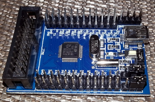
The final topic is about loading code to a STM32 micro. There are two ways either by a JTAG programmer like ST-Link or by bootloader and UART. The former is the best choice as it is a programmer and a debugger but in terms of expense this is unnecessary as the chips come with preprogramed bootloader. Thus the latter method of using bootloader and UART is simplest and also the most popular solution. This is also my personal preference as I didn’t want to spend for another programmer just for the purpose studying. This is the method I’ll describe here. Let’s see the board:

This baby is about the size of a standard match box and contains the basic components needed for its STM32F108C8 micro. This one comes from LC-Technology China (http://www.lctech-inc.com/Hardware/Detail.aspx?id=0172e854-77b0-43d5-b300-68e570c914fd) and is reasonably cheap. I have also other ARM boards but this one is my favourite because of its compact size and portability. Most STM32F10x board have similar features and no matter what board is chosen there’ll literally no difference at all.
Now let’s see the important parts of the board:
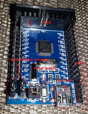
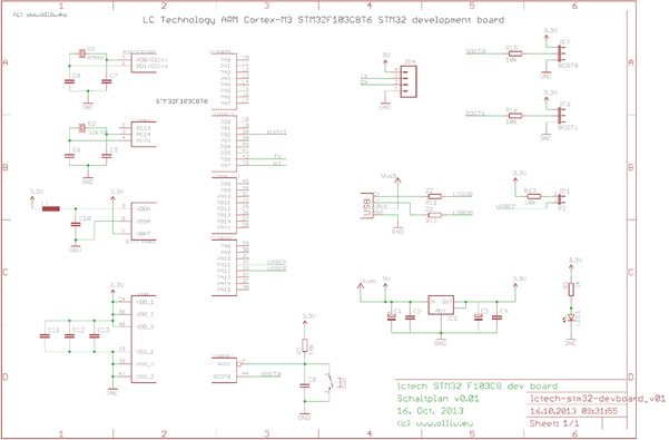
These are the least common features of any STM32 development board must have. Here’s the schematic of the board:
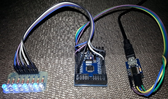
To demonstrate Flash Loader Demonstrator I made a setup for a wasteful LED blinking project with STM32 just for the sake of giving a demo. Here’s the setup:
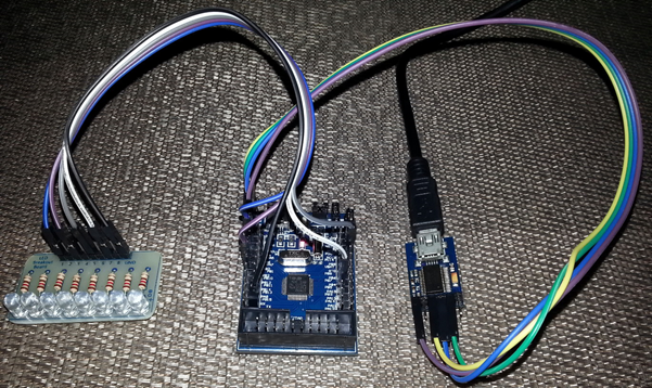
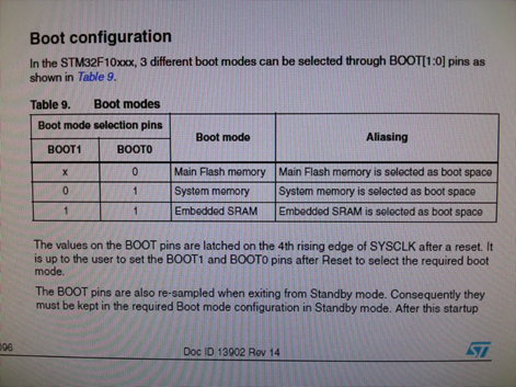
The needed tools here are a PC, a FT232 USB-UART converter, a LED breakout board and of course a STM32 board. Since the micro is empty the LEDs are all off. Now let’s upload a code in it. Before we do that please have a look in “Boot Configuration” section of STM32F103’s reference manual and also locate the boot jumpers of your board. Usually Boot 0 is kept low and Boot 1 high to enter bootloader mode after reset.
The first photo below shows the jumper settings during normal running and the second shows the settings needed during uploading code. Every time the jumpers are altered a reset is a must. To do so just hit the reset switch briefly.
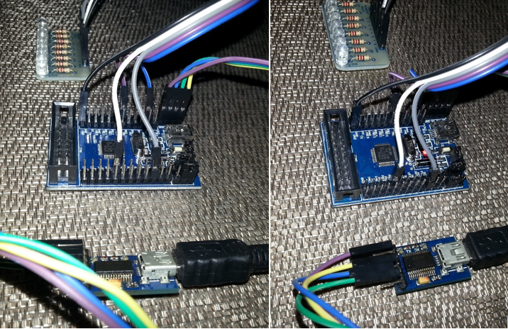
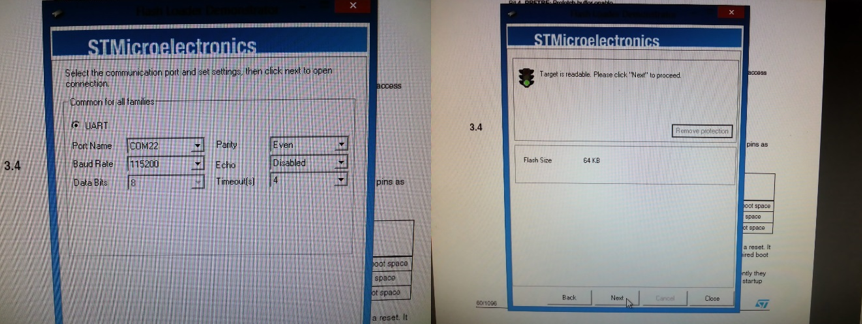
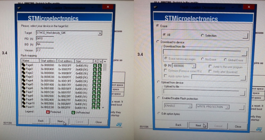
Be sure to change jumpers when changing modes. Shown below are step-step ways of loading a code using boot loader and UART. Prior to entering boot loader mode change the jumper and hold reset before clicking “Next” in the Flash Loader Demonstrator GUI. This is similar to entering the boot loader mode of an Arduino but manually.

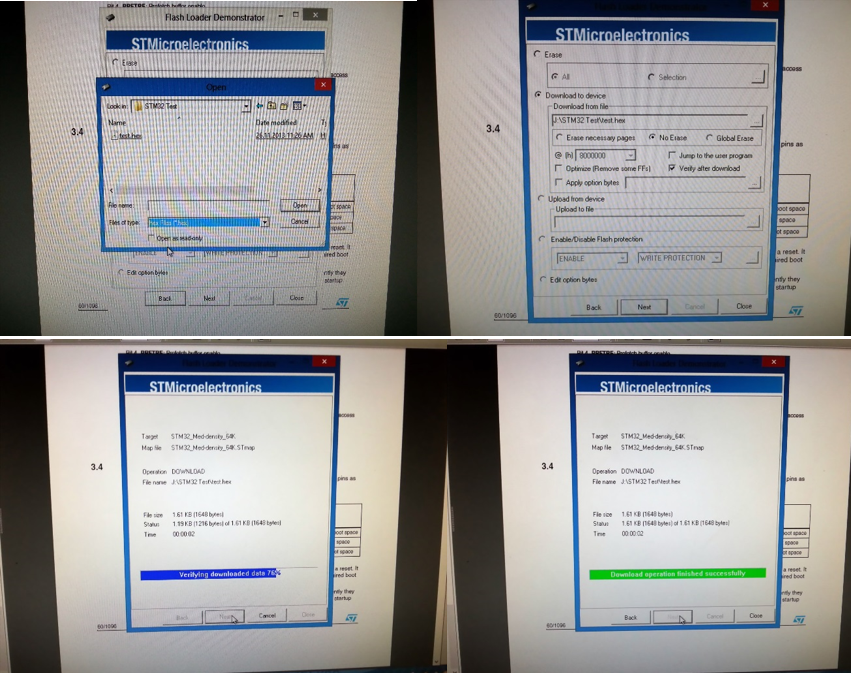
After flashing the STM32, the code runs as shown below:
I hope it was helpful. Happy coding.
Repository: https://github.com/sshahryiar/STM32-Tutorials
Author: Shawon M. Shahryiar
https://www.youtube.com/c/sshahryiar
|
|
You and your readers might be interested in a STM32 tutorial series I wrote on my blog. The first article can be found at http://thehackerworkshop.com/?p=391