Tag Archives: Advanced Embedded-Systems


STM32 Digital-to-Analogue Converter (DAC)

After having played with Analogue-to-Digital Converter (ADC) of STM32 micros, the obvious next internal hardware block to deal with is the Digital-to-Analogue Converter (DAC). As the name suggests this block has just the complementary function of ADC. It converts digital binary values to analogue voltage outputs. The DAC block has several uses including audio generation, waveform generation, etc. Typically in most 8-bit micros, this block is unavailable and its need is somewhat loosely met with Pulse Width Modulation (PWM) block. This is partly because of their relatively less hardware resources and operating speeds. All STM32 micros also have PWM blocks but large capacity STM32s have DAC blocks too. The STM32 DAC block is not very complex and has similarity with the ADC block in terms of operating principle. The simplified block diagram below shows the major components of the STM32 DAC block.

Block Diagram Read more

Integrating STM32F4xx Standard Peripheral Library with MikroC Pro for ARM

STM32F4xx series micros are far more advanced than anything else similar in the market. Apart from being fast 32-bit MCUs, STM32F4s have rich hardware peripheral support with DSP engine bonus. In terms of capabilities versus price tag, STM32F4s are all-square-winners. In recent times there’s a surge in the STM32 user community. STM32 Discovery boards are proliferating like never before. In several occasions recently, I received tangible amounts of queries from readers regarding integration of STM32F4xx Standard Peripheral Library (SPL) with MikroC Pro for ARM and so even though it is not one of my mainstream posts on STM32 ARMs, I felt that I should address this topic. Previously I showed how to port STM32F1xx SPL for STM32F1xx series devices with MikroC. This post will not be different from the former one – only minute changes. I suggest readers to read the earlier post first before reading this one. STM32F4 Discovery Board

Read more

STM32 GPIO Ports Insights

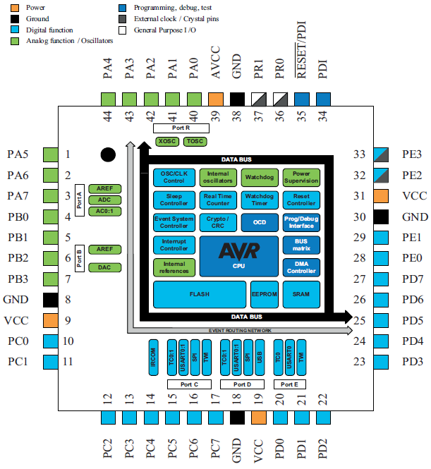
In any microcontroller there is at least one general purpose input-output port. STM32 is a not different breed and as expected it also has several GPIO ports. These ports are usually named GPIOA, GPIOB, etc. but unlike most 8/16-bit micros these ports are 16 bit wide. Thus, in general, every port has 16 IO pins. Port pins have several modes of operation and this is what that makes them both robust and complex at first. In development boards the IO port pin naming is cut short and so we’ll find PA0, PB12, etc. instead of GPIOA0, GPIOB12, etc. Even in the reference manuals this short naming is used widely. In the end every I/O pin is general purpose in nature.

Key points with STM32’s GPIO

  • Upon any reset event all GPIOs are floating inputs. This prevents any accidental damage to GPIOs in the event of emergency.
  • All GPIO registers are needed to be accessed with 32 bit words. This is mandatory.
  • Reserved bits for any GPIO register are kept at reset values i.e. 0.
  • For every GPIO port there are seven registers but the only the first four are the most important ones. The rest can be ignored most of the times.
  • These important GPIO registers per port are CRL, CRH, IDR and ODR. The rest three registers for GPIO ports can be avoided at the beginning.
  • For bit set and for bit clear, operations REGx |= (1 << bit) and REGx &= ~ (1 << bit) respectively are very handy and efficient. However MikroC compiler provides bit level access though its internal header file coding like this GPIOB_BSRRbits.BS15. We can use this method or the other one.
  • Some IOs are 5V tolerant and are label “FT” in datasheets and other docs. The rest of the I/O pins are not that tolerant and so 3.3V operation should always be ensured. STM32 has a maximum VDD tolerance of 4V but this value shouldn’t be used in any situation for safe operation. Best is to avoid 5V use with GPIOs whenever possible. This will help in avoiding accidental damage to the micro due to common mistakes.
  • Unused GPIO pins should be kept at reset state or tied to ground with 10kΩ resistors so that they remain either as floating inputs or safely connected to ground though it’s not a must.
  • I/O pins can source or sink currents up to 25mA. Thus direct LED drive is possible with them. To drive loads that need more than this value, we must use external BJTs, MOSFETs, optocouplers, transistor arrays or other driver devices.
  • I/O pins should not directly drive inductive or capacitive loads.
  • Care should be taken to avoid driving outputs beyond 50MHz. This is the maximum I/O pin frequency rating.
  • CRL/H registers essential set GPIO pin operating mode independently as according to the table below:

Port Configurations

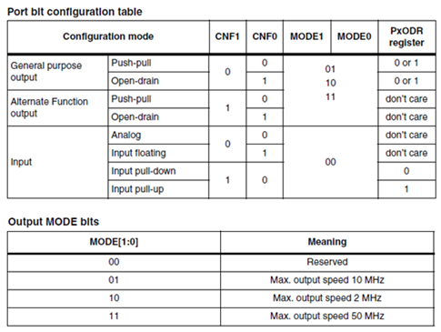
  • CRL sets GPIOs from 0 – 7 while CRH sets from 8 – 15. All IO ports are 16 bit wide unlike common 8 bit micros like PIC or AVR.

Read more

STM32 Programming Tips and Tricks

I remember that once in the beginning I said that I don’t want to buy a programmer/debugger hardware for learning a new MCU like the STM32 and also STM32s already come with built-in bootloader to facilitate programming via USART just like Arduino. Still the second is true. Well what about the first? To my own surprise I actually acquired a number of STM32-related stuffs since the time I started playing and exploring them. I actually bought both ST-Link 1 and 2 programmer-debuggers and several STM32 boards from Waveshare Electronics (http://www.wvshare.com). I believe learning new stuffs is more valuable than anything else.

ST-Link Programmer/Debugger

ST-Link 1 (AKA ST-Link) and ST-Link v2 are both basically the same programmer/debugger hardware with some minor exceptions. ST-Link 2 has 5V tolerance for JTAG interface, it has a bicolour status LED and it also has a separate programming interface for STM8 micros unlike ST-Link 1. There is also an ISOL version of ST-Link2 that galvanically isolates it from its target using optoelectronics.

stlinkgreycablewhite

ST-LINKV2_3

Read more

XMega I/O Ports

Any microcontroller must have I/O pins for taking inputs and providing outputs. The ATXMega32A4U just like any other micro has 34 programmable I/O pins divided unevenly amongst six IO ports. Most I/O ports are 8 bit wide. XMega I/Os have digital, analog and special purpose functions. Some I/O pins have more than one use. A quick view of the XMega I/O pins reveals the purpose of these pins.

XMega Interior

Read more

« Older Entries