Tiva C GPIOs
|
|
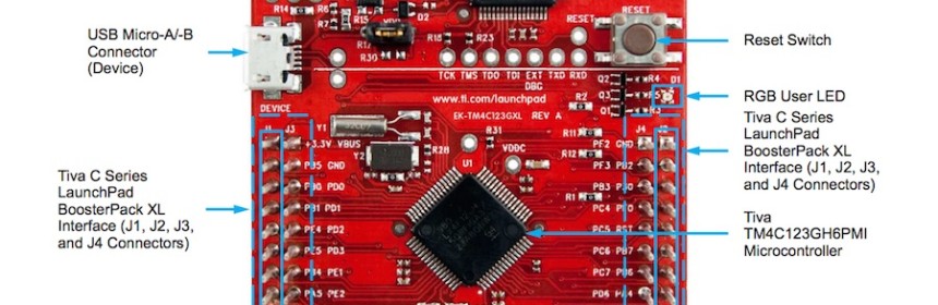
GPIOs are the basic interfaces of any microcontroller. Without GPIOs we won’t have any other way to use a micro and it will be nothing more different than a chunk of well-fabricated silicon. Through them we can interface both transducers or sensors and actuators. We can also connect other devices like a display, external devices and so on. As with any ARM microcontroller, the GPIOs of TM4C12x Tiva C ARM microcontrollers are very elaborate, having many options that are usually unavailable in common 8-bit microcontrollers. The one we are interested in – the TM4C123GH6PMI – is a 64-pin micro with more than 40 usable GPIO pins. Here in this post we will explore the GPIOs of TIVA C micros.
Overview
Tiva C micros are low power ARM Cortex M4 MCUS and run typically at 3.3V and so you can guess the logic levels of GPIO pins. However, except a few GPIOs (PB0, PB1, PD4 and PD5) all GPIO pins are 5V tolerant. This 5V tolerant feature is a smart addition and most people will simply overlook it or won’t fully realize its potential use. At present microcontrollers are getting more and more energy efficient, and so their operating voltage levels are gradually decreasing. Most modern micros, especially the ARM family don’t operate at 5V and the use of 5V TTL logic level will eventually diminish in the future. The most common new voltage standard is that of a cell phone, i.e. 3.3V. Many microcontrollers like the ATMega16A and the PIC18F252 that usually operate at 5V have the ability to operate at 3.3V or even below. However, there are lots of other devices that can’t operate below 4V. These devices will operate erroneously or may even reset frequently due to brownout. Here the 5V tolerant feature of Tiva C MCUs come to aid, allowing us to use legacy external interfaces and devices like sensors, external modules, legacy microcontrollers, etc. without the need of additional logic level translator circuits or too much consideration about different voltage levels. It is as simple as plug-and-play. Thus, cost, space and size remain at a minimum.
At this point we need to note a few things:
- Never exceed input logic high voltage of any pin beyond VDD limit unless you are sure that the source will not exceed the 5V limit and you aren’t using the any of the exceptional pins (PB0, PB1, PD4 and PD5). It is better to leave these pins idle unless you have memorized these pin numbers. Fortunately, PD4 and PD5 are inaccessible in the Tiva C Launchpad board.
- Likewise, don’t use negative input voltages with any pin. Be sure of polarity.
- Some GPIO pins are not accessible in Launchpad board while others are physically non-existent, e.g. PF7 and so don’t try to program them. Leave them alone just like a don’t care bit of a register.
- When coding a new project, I recommend adding a delay of about 2 – 3 seconds at the start of the code to avoid part lockout.
- Don’t stress any GPIO pin beyond 10 – 15mA, although the max limit is 25mA. Use external switching devices like opto-isolators, FETs and BJTs to drive high power loads.
- Though most pins are 5V tolerant, it doesn’t necessarily mean that the logic level is based on 5V TTL logic level. The logic level voltage limits are still realized with respect to VDD, 3.3V.
- Similarly, when using TIVA C micro’s ADC, the ADC pins can withstand voltages beyond VDD voltage limit but can’t measure voltages beyond VDD or reference voltage level.
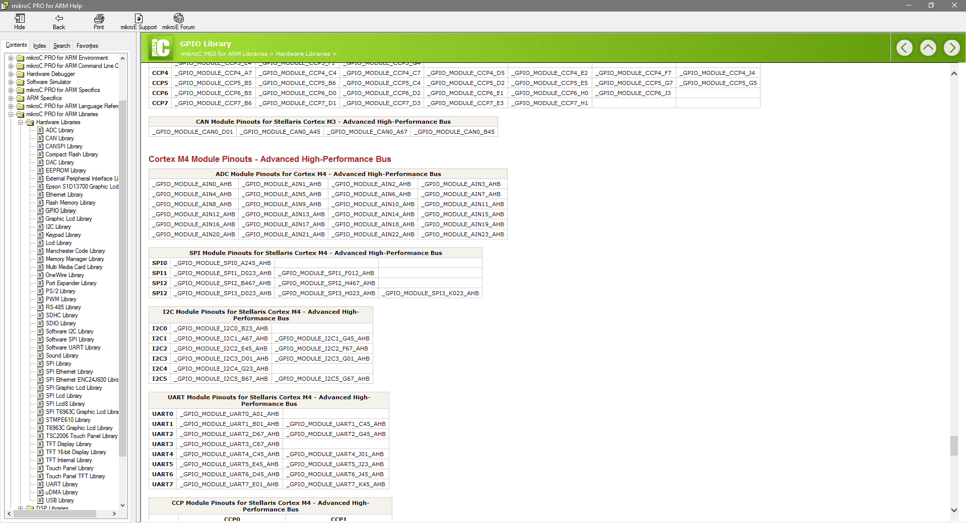
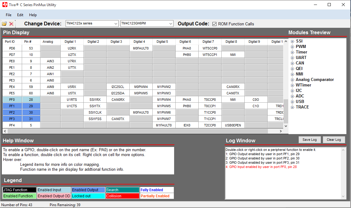
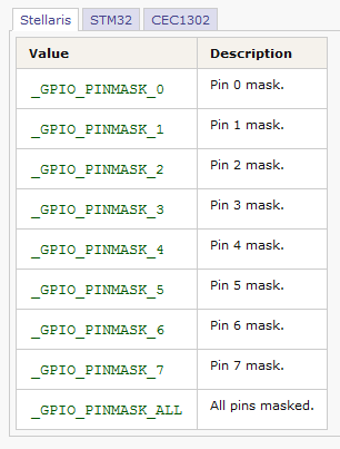
- GPIO pins have alternate functions and so use Pinmux software to find required GPIO pins. You can also checkout the alternate function pins in the help section of MikroC compiler under the GPIO library. In the compiler, if you type _GPIO and hit CTRL + Space, you’ll see all available options for GPIO.
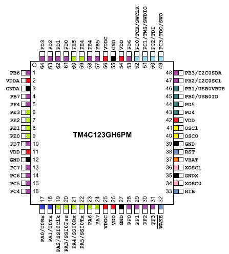
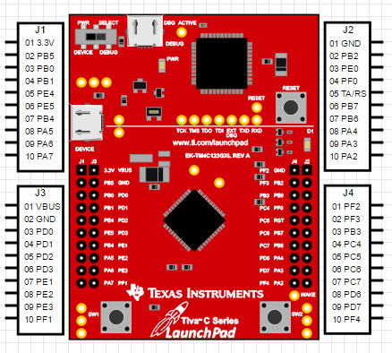
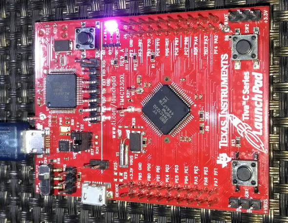
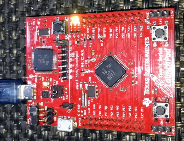
Both the GPIOs and their registers are all 8-bit wide just like 8-bit micros but there are many registers and options related to each port pin. We can code these registers on our own or use MikroC compiler’s GPIO Library and get GPIOs working. Here I’m preferring the use of MikroC’s library functions because this library allows us to set every option related to GPIOs much more easily and quickly than it would have been otherwise. We will still have an overview of the registers. Please note that neither will you find GPIO Library in the compiler’s Library Manager nor will it be needed to add this library in a project like other built-in libraries. This is because GPIOs are the most common things we use in a micro and so, by default, GPIO Library is added by the compiler whenever we start a new project. The compiler’s help documentation on GPIO Library is as good as the datasheet itself. All we need is the pin map as shown below. The pin names and numbers are also inscribed in the board.
One personal experience I would like to share here. I have been working with STM32 ARMs for quite a long time and I love STM32 family a lot. One key advantage with STM32s is the 16-bit port width. In some applications, this feature helps a lot as we can use the GPIOs to form 16-bit parallel ports intended for 6800 and 8080 interfaces. For example, in popular TFT display like ILI9325, it is required to send/receive instructions to and from the display as 16-bit chunks. With only one C instruction, we can complete one 16-bit transfer sequence unlike what we have been doing previously in 8-bit systems, i.e. breaking a 16-bit value into two 8-bit values and then transferring it sequentially one after another. This save time and requires less coding. It also makes the displays perform faster than otherwise. However, for Tiva C ARMs and other advanced MCUs like the Atmel ATXMega series, this same task needs to be done twice due to 8-bit port width. This isn’t a design flaw or some kind of serious issue with these MCUs. Having things in 8-bit format isn’t bad, in fact it is often a time-saver in another way. We can easily manipulate 8-bit stuffs more quickly and easily than higher bit order stuffs. It is something we have inherited from our previous 8-bit MCU experiences.
When comparing Tiva C ARMs with respect to the popular STM32F1 series flagship ARMs, we need to look at two things also. STM32F1 series can operate at a max clock speed of 72MHz while Tiva C ARMs are slightly faster and can operate at a max clock speed of 80MHz. STM32F10x series is based on Cortex M3 architecture while Tiva C ARMs are based on Cortex M4 architecture. This gives Tiva C ARMs an edge over the STM32F1s. However, STM32F4 and STM32F7 series, which are also based on Cortex M4, are even better. The point here is not the comparison of MCU families and choice but to show that each family have their own disadvantages and advantages that we only need to consider when things demand so. Every MCU is good and it depends how we are going to use it. Fortunately, MikroC for ARM allows us to try out different ARM families with minimum efforts and low cost.
Basic Architecture
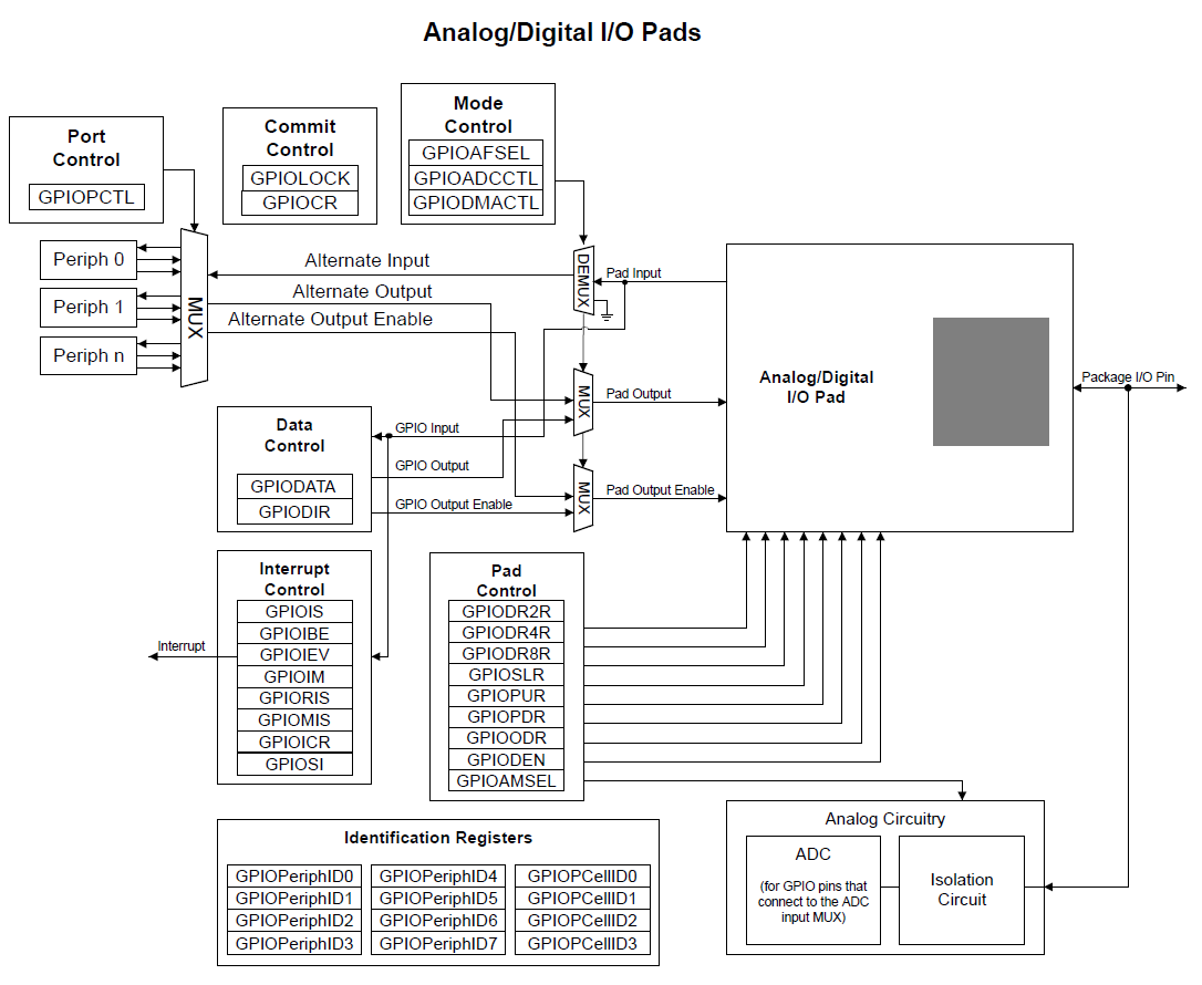
In the block diagram shown below we can see the internal architecture of a Tiva C GPIO pin. The first thing that will strike our mind is the number of registers attached to a pin and thereby the several options a GPIO pin possesses.
Some key highlights of the GPIOs are as follows:
- All pins have internal input pull-up and pull-down resistors.
- Pins can be configured as GPIOs or as AFIOs for other special purpose like SPI, I2C, etc.
- Any pin can be used for external interrupt, ADC trigger and DMA trigger.
- Pin states can be retained during hibernation mode.
- Schmitt-triggered digital input pins.
- GPIO input pins are 5V tolerant.
Registers
From the internal architecture block diagram, we have seen that every GPIO pin has many registers associated. Shown below is a reduced register map:
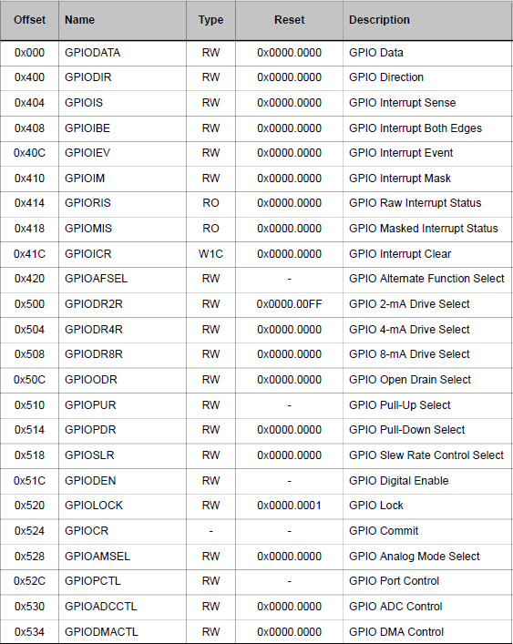
As you can see there are too many things to configure and this is still not the complete register map. However, for most applications we’ll need GPIODATA and GPIODIR registers. Their names suggest their purpose. GPIODIR register sets GPIO direction – input/output. Clearing its bits set corresponding GPIO pins as inputs and setting them set pins as outputs. GPIODATA register is used to write to/read from GPIO pins. The rest of the registers are for external interrupts, triggers for DMA and ADC, and for advanced customization of GPIO pins.
When coding in raw level, we also need to take care of enabling/disabling the clocks of GPIOs. This is one by using the registers of system control block. Check General-Purpose Input/Output Run Mode Clock Gating Control (RCGCGPIO) register.
MikroC GPIO Library
The following are the built-in GPIO library functions:
- GPIO_Clk_Enable
- GPIO_Clk_Disable
- GPIO_Unlock
- GPIO_Lock
- GPIO_Config
- GPIO_Set_Pin_Mode
- GPIO_Digital_Input
- GPIO_Digital_Output
- GPIO_Analog_Input
- GPIO_Alternate_Function_Enable
- __mE_Lib_GPIO
Of these 11 functions, we’ll need only the following six for most applications:
- GPIO_Clk_Enable – enables a GPIO port’s clock.
- GPIO_Clk_Disable – disables a GPIO port’s clock.
- GPIO_Unlock – unlocks GPIO pins.
- GPIO_Lock – locks GPIO pins
- GPIO_Config – sets up GPIO pin functionalities, direction and properties.
- GPIO_Alternate_Function_Enable – specifies alternate function pins and enables them.
The rest, except the __mE_Lib_GPIO are basically extensions of GPIO_Config function and so we won’t be needing them. GPIO_Config function is more than enough.
We will understand well how these functions work when we check out the code examples. For now, have look at the Launchpad boards schematic. Notice the red highlighted areas. We’ll be using these.

LM Flash Programmer
For physically programming the Tiva C Launchpad board, we’ll need a programmer or bootloader. I’m not interested in the latter as all Tiva C Launchpad boards came with on board programmer hardware. Bootloaders are also sometimes unreliable. All we need to use the programmer is a software. LM Flash programmer is that software. It has a simple GUI interface and is quite similar to other program-uploading software. It can be freely downloaded from http://www.ti.com/tool/lmflashprogrammer.
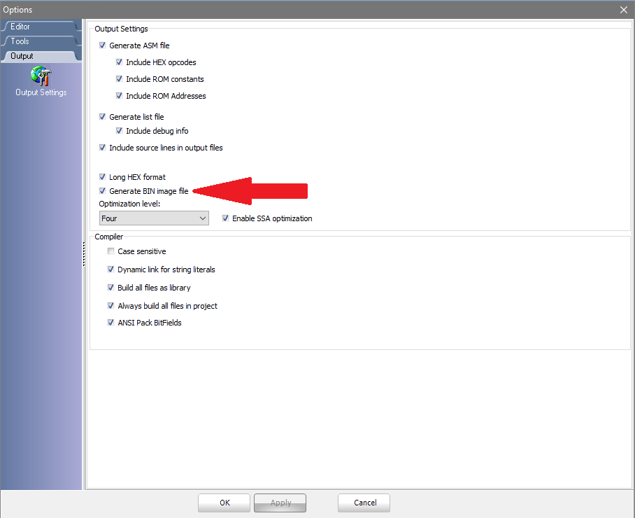
The only different thing one may encounter is the file format that can be uploaded. So far most of us know that hex files are the ones that are finally uploaded to micros. However, there are other file formats that can be uploaded too. LM Flash programmer requires a binary file instead of a hex file. Uploading a hex file won’t simply work. Thus, we have to instruct our compiler to generate binary (bin) files along with hex files. In MikroC IDE, press F12. Compiler options window will popup. Just tick the checkbox as shown below. Now MikroC compiler will also generate binary images.
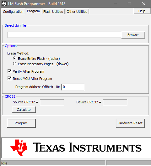
LM Flash programmer GUI looks like as shown below.
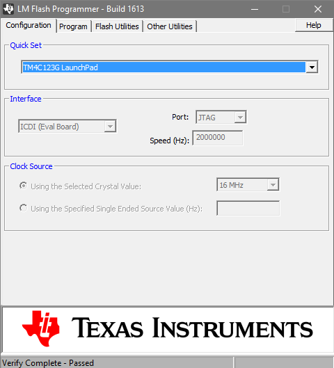
It is a very easy to use software. All we need to do is to select the proper Launchpad board and show it the path to the binary file we wish to upload.
Code Examples
LED Blinking Example
The very first project that we always do when we try out a new MCU is a simple LED blinking. This is also my first example. In this example, I lit the on-board RGB LED in a colour mixer pattern. Here’s the code:
void setup_GPIOs();
void main()
{
setup_GPIOs();
while(1)
{
GPIO_PORTF_DATA1_bit = 1;
GPIO_PORTF_DATA2_bit = 0;
GPIO_PORTF_DATA3_bit = 0;
delay_ms(900);
GPIO_PORTF_DATA1_bit = 1;
GPIO_PORTF_DATA2_bit = 1;
GPIO_PORTF_DATA3_bit = 0;
delay_ms(900);
GPIO_PORTF_DATA1_bit = 0;
GPIO_PORTF_DATA2_bit = 1;
GPIO_PORTF_DATA3_bit = 0;
delay_ms(900);
GPIO_PORTF_DATA1_bit = 0;
GPIO_PORTF_DATA2_bit = 1;
GPIO_PORTF_DATA3_bit = 1;
delay_ms(900);
GPIO_PORTF_DATA1_bit = 0;
GPIO_PORTF_DATA2_bit = 0;
GPIO_PORTF_DATA3_bit = 1;
delay_ms(900);
GPIO_PORTF_DATA1_bit = 1;
GPIO_PORTF_DATA2_bit = 0;
GPIO_PORTF_DATA3_bit = 1;
delay_ms(900);
GPIO_PORTF_DATA1_bit = 1;
GPIO_PORTF_DATA2_bit = 1;
GPIO_PORTF_DATA3_bit = 1;
delay_ms(900);
}
}
void setup_GPIOs()
{
delay_ms(2000);
GPIO_Clk_Enable(&GPIO_PORTF);
GPIO_Config(&GPIO_PORTF,
(_GPIO_PINMASK_1 | _GPIO_PINMASK_2 | _GPIO_PINMASK_3),
_GPIO_DIR_OUTPUT,
(_GPIO_CFG_DIGITAL_ENABLE | _GPIO_CFG_DRIVE_8mA),
_GPIO_PINCODE_NONE);
}
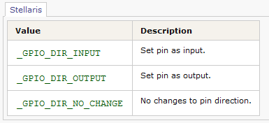
As you can see the GPIO_PORTF_DATA registers are being used to light the LEDs. However, we need to configure these pins before we can use them. In the setup_GPIOs() function, pins 1 through 3 of GPIO PORTF are configured as outputs. Firstly, we need to enable the clock for the GPIO that we are wanting to use. Library function GPIO_Clk_Enable() does that. This is followed by actual GPIO setup. We need PF1, PF2 and PF3 – the RGB LED pins, to be outputs. This is done by GPIO_Config() library function. This function has several argument parameters that define GPIO properties. The first argument states which GPIO port we are concerned with. The second masks the required pins. The third selects GPIO direction. Finally, the last parameters further select what features we want from these pins. More details on what each argument parameter means is detailed in the compiler’s help documentation. Just be sure that you selected the right ARM family. In case of Tiva C MCUs we should check out which functions and options are valid for Stellaris family. Stellaris is the predecessor of Tiva C micros.

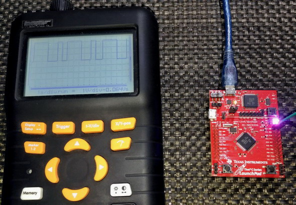
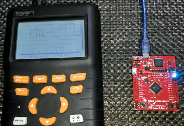
If you remember my previous post on Tiva C clock system, you’ll remember that I stated that we’ll reverify our clock settings in this post. In the example, we saw that at every 900ms the state of the GPIOs changed in a grey-code-like fashion. To verify clock settings, I hooked up an oscilloscope with one GPIO pin. Here’s the result:
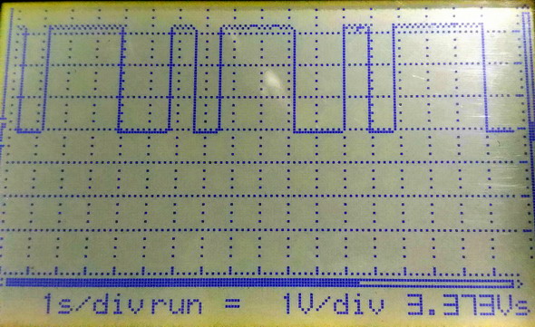
The scope has been set to one second per division. The smaller square waveforms are a bit shorter than one complete division. As can be seen, the timing is perfect and so is our clock setting.

Demo video clip: https://www.youtube.com/watch?v=4mJ6A8wkbdY.
Reading Inputs
This example demonstrates how to read GPIO pins. Again, refer to the Launchpad board schematic. There are two user buttons on board. In this example, we’ll use both to change the RGB LED’s colour. Apart from configuring the GPIOs, an extra step will be needed.
There are certain special pins in the TM4C123GH6PMI MCU that, by default, can’t be used like other GPIOs. They are attached to important hardware like JTAG, NMI, etc. In terms of hardware, these pins are locked from ordinary uses. Thus, we’ll be needing to unlock them if we are to use them as ordinary GPIOs. The SW2 button on the Tiva C Launchpad board is shared with NMI and we can’t use it unless we unlock it. This is the extra step.
Both SW1 and SW2 – momentary pushbuttons are attached directly with the PF4 and PF0 respectively. There are no pull-up or pull-down resistor attached with them. Thus, we will be needing to enable internal pull-up resistors. Here’s the code example.
#define user_button1 GPIO_PORTF_DATA0_bit
#define user_button2 GPIO_PORTF_DATA4_bit
#define red_LED GPIO_PORTF_DATA1_bit
#define blue_LED GPIO_PORTF_DATA2_bit
#define green_LED GPIO_PORTF_DATA3_bit
void setup_GPIOs();
void main()
{
signed char s = 0;
setup_GPIOs();
while(1)
{
if(user_button1 == 0)
{
while(user_button1 == 0);
s++;
}
if(s > 7)
{
s = 0;
}
if(user_button2 == 0)
{
while(user_button2 == 0);
s--;
}
if(s < 0)
{
s = 7;
}
switch(s)
{
case 1:
{
red_LED = 1;
green_LED = 0;
blue_LED = 0;
break;
}
case 2:
{
red_LED = 0;
green_LED = 1;
blue_LED = 0;
break;
}
case 3:
{
red_LED = 0;
green_LED = 0;
blue_LED = 1;
break;
}
case 4:
{
red_LED = 1;
green_LED = 1;
blue_LED = 0;
break;
}
case 5:
{
red_LED = 1;
green_LED = 0;
blue_LED = 1;
break;
}
case 6:
{
red_LED = 0;
green_LED = 1;
blue_LED = 1;
break;
}
case 7:
{
red_LED = 0;
green_LED = 0;
blue_LED = 0;
break;
}
default:
{
red_LED = 1;
green_LED = 1;
blue_LED = 1;
break;
}
}
}
}
void setup_GPIOs()
{
delay_ms(2000);
GPIO_Clk_Enable(&GPIO_PORTF);
GPIO_Unlock(_GPIO_COMMIT_PIN_F0);
GPIO_Config(&GPIO_PORTF,
(_GPIO_PINMASK_0 | _GPIO_PINMASK_4),
_GPIO_DIR_INPUT,
(_GPIO_CFG_PULL_UP | _GPIO_CFG_DIGITAL_ENABLE),
_GPIO_PINCODE_NONE);
GPIO_Config(&GPIO_PORTF,
(_GPIO_PINMASK_1 | _GPIO_PINMASK_2 | _GPIO_PINMASK_3),
_GPIO_DIR_OUTPUT,
(_GPIO_CFG_DIGITAL_ENABLE | _GPIO_CFG_DRIVE_8mA),
_GPIO_PINCODE_NONE);
}
Demo video clip: https://www.youtube.com/watch?v=tyCTbwEJshI.
Tiva C GPIO Files: tiva-c-gpio-files.
Happy coding.
Author: Shawon M. Shahryiar
https://www.facebook.com/MicroArena
14.10.2016
*Some images are taken from TI’s websites and datasheet, and MikroC for ARM compiler.
|
|