Using Fixed Voltage Reference (FVR) for A/D conversion in enhanced mid-range PIC microcontrollers
|
|
The reference voltage plays a very important role in any A/D conversion. It determines both the range and the resolution (Volt/Count) of the A/D conversion. Besides, the accuracy of the conversion also depends upon how stable the reference voltage is. Usually in PIC microcontrollers, the reference voltage for A/D conversion can be selected as the supply voltage itself or provided externally through one or more I/O pins. But the new enhanced mid-range family of 8-bit PIC microcontrollers have a built-in module that generates a stable reference voltage internally. It is called Fixed Voltage Reference (FVR) where the output is very stable and independent of the supply voltage (VDD). The output of the FVR can be configured to supply a reference voltage for A/D conversion internally. This article describes how to configure the FVR module to derive the reference voltage of 2.048 V for A/D conversion in PIC16F1827 microcontroller. The analog signal for this experiment is taken from the output of a LM34DZ temperature sensor. After the A/D conversion, the PIC16F1827 displays the temperature on a 2×8 character LCD.

Using internal FVR for A/D conversion of LM34 analog output
Theory
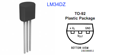
LM34DZ temperature sensor

LM34DZ pin diagrams
Fixed Voltage Reference (FVR) in PIC16F1827
PIC16F1827 is a member of Microchip’s enhanced mid-range 8-bit microcontroller family. It is pin-compatible with the popular 18-pin predecessors such as PIC16F628A and PIC16F88, but is equipped with lot more peripherals and other features. The Fixed Voltage Reference (FVR) module in PIC16F1827 generates a stable voltage reference internally. The FVR output provides three software selectable voltage levels, 1.024V, 2.048V and 4.096V. The output can be configured to supply a reference voltage to the following:

FVRCON register (the bit values shown configures FVR to 2.048 V for ADC purpose)
Once the FVRCON register is configured, the choice of reference voltage for A/D conversion is made through ADCON1 control register. By setting ADPREF<1:0> bits to ‘1’, the positive reference voltage for A/D conversion is derived from the internal FVR module. Clearing the ADNREF bit connects the A/D negative reference voltage pin to the ground (VSS).

Use ADCON1 register to select the reference voltage source for ADC
Once the reference voltage is selected, the rest of the A/D conversion process is similar to any other PIC microcontroller.
Why the reference voltages are 1.024, 2.048, or 4.096 V?
The reason for the reference voltage to be non-integer numbers like these is to provide a precise resolution in A/D conversion. For example, if the positive A/D reference is 2.048 V and the negative reference is 0 V, then the resolution of 10-bit A/D conversion is 2.048 V/ 1024 = 2 mV/Count. This means, in order to get the analog value (in mV) back from the digital count, you just need to multiply the count by 2. Similarly, the positive reference voltage of 4.096 V gives the conversion resolution of 4 mV/Count. This makes the calculations easier and accurate.
Circuit diagram
The circuit diagram for this experiment is simple. The LM34DZ and the microcontroller circuit are powered with a +5V supply. The output voltage of LM34DZ sensor is fed to the AN0 ADC channel of PIC16F1827. The microcontroller runs at 500 KHz internal clock. The LCD display is operating in 4-bit data mode. The D4-D7 data pins are driven through RB4-RB7 port pins, respectively. The RB2 (8) and RB3 (9) I/O pins control the RS and E signals of LCD display. A 5K potentiometer is used for adjusting the contrast of the LCD display.

Circuit diagram for reading the analog output from LM34DZ

Displaying temperature on LCD screen
Software
The use of internal reference voltage for A/D conversion requires configuration of FVRCON and ADCON1 registers. The mikroC Pro for PIC compiler provides a library for A/D conversion, but that uses the supply voltage, VDD , by default as the positive reference for the conversion. So the built-in ADC library of mikroC Pro for PIC is not useful for our case. The following program is written for PIC16F1827 without using the built-in ADC library and it allows to use the stable FVR output as the positive voltage reference for A/D conversion. We will use 2.048 V reference voltage from the FVR module for the A/D conversion. This will limit the maximum value of the input analog signal to 2.048 V. Since we are using the LM34DZ output for the analog signal, this limits the maximum value of the measurable temperature to 204.8?F. For measuring temperatures higher than that, the reference voltage of 4.096 may be used.
ADC Math
ADC Resolution = 2.048 V/1024 count = 2 mV/count
=> LM34DZ output voltage (mV) = 2 x count
Temperature (?F) = LM34 output voltage (mV)/10
=> Temperature (?F) = 2 x count/10 = count/5
/*
  Description: Use internal 2.048 V FVR for A/D conversion
  of LM34DZ output
  MCU: PIC16F1827, 500 KHz internal clock, MCLR enabled
  Jul 2, 2011
*/

// Define LCD connections
sbit LCD_RS at RB2_bit;
sbit LCD_EN at RB3_bit;
sbit LCD_D4 at RB4_bit;
sbit LCD_D5 at RB5_bit;
sbit LCD_D6 at RB6_bit;
sbit LCD_D7 at RB7_bit;
sbit LCD_RS_Direction at TRISB2_bit;
sbit LCD_EN_Direction at TRISB3_bit;
sbit LCD_D4_Direction at TRISB4_bit;
sbit LCD_D5_Direction at TRISB5_bit;
sbit LCD_D6_Direction at TRISB6_bit;
sbit LCD_D7_Direction at TRISB7_bit;
// End LCD module connections

// Define Messages
 char message1[] = "Temp.";
 char *Temp = "000.0 F";
 unsigned ADC_Value, Temp_F;

void main() {

 ANSELA = 0b00000001;  // RA0 analog input
 TRISA  = 0b00100001;  // RA0, RA5 inputs
 ANSELB = 0b00000000;  // PORTB all digital outputs
 TRISB  = 0b00000000;  // PORTB all outputs

 // Configure FVR to 2.048 V for ADC
  FVRCON = 0b11000010 ;

  // Configure ADCON1
  ADCON1.ADNREF  = 0;  // Vref- is connected to ground
  ADCON1.ADPREF0 = 1;  // Vref+ is connected to internal FVR
  ADCON1.ADPREF1 = 1;
  ADCON1.ADCS0   = 0;  // Use conversion clock, Fosc/2
  ADCON1.ADCS1   = 0;  // Fosc = 500 KHz
  ADCON1.ADCS2   = 0;
  ADCON1.ADFM    = 1;  // result is right Justified

  // Configure ADCON0 for channel AN0
  ADCON0.CHS0 = 0;
  ADCON0.CHS1 = 0;
  ADCON0.CHS2 = 0;
  ADCON0.CHS3 = 0;
  ADCON0.CHS4 = 0;
  ADCON0.ADON = 1;  // enable A/D converter

  // Initialize LCD
  Lcd_Init();                  // Initialize LCD
  Lcd_Cmd(_LCD_CLEAR);         // CLEAR display
  Lcd_Cmd(_LCD_CURSOR_OFF);    // Cursor off
  Lcd_Out(1,2,message1);       // Write message1 in 1st row

 do {

  ADCON0.F1 = 1;        // start conversion, GO/DONE = 1
  while (ADCON0.F1);    // wait for conversion
  ADC_Value = (ADRESH << 8 ) + ADRESL;
  Temp_F = ADC_Value * 10/5;
  Temp[0] = Temp_F/1000 + 48;
  Temp[1] = (Temp_F/100)%10 + 48;
  Temp[2] = (Temp_F/10)%10 + 48;
  Temp[4] = Temp_F%10 + 48;
  if (Temp[0] == '0')                       // if Temp[0] = '0' then
      Temp[0] = ' ';                        // insert blank character to Temp[0]
  if (Temp[0] == ' ' && Temp[1] == '0')     // if Temp[0] is blank and Temp[1] =
      Temp[1] = ' ';                        // '0' then
  Temp[5] = 223;
  LCD_Out(2,2, Temp);
  Delay_ms(1000);
 } while(1);
}
Download the source code and HEX files
Conclusions
A stable reference voltage is required in A/D conversion systems for accurate and repeatable data conversion. While this can be achieved externally by using precision voltage regulators or zener diodes, the enhanced mid-range 8-bit PIC microcontrollers facilitate this feature internally through the FVR module, thus avoiding the use of any external components. The use of internal FVR module also frees the external Vref pin, which means an extra GPIO pin. The microcontroller’s power supply voltage (typically +5V) itself can be used as the reference voltage for A/D conversion. While this allows the maximum range for A/D conversion, it could possible introduce errors in the conversion if the supply voltage is not stable (usually the supply voltage drifts with load conditions). Besides, if the range of the analog signal is much lesser than the supply voltage, it is always good to use a lower reference voltage for achieving higher resolution. The FVR module inside the 8-bit PIC microcontrollers of the enhanced mid-range family provides three stable and configurable reference voltages internally, which makes the design of data conversion systems more flexible and easier.
|
|
Thanks for this. I am also looking at using the FVR on another device (18F13K22) but am not too impressed that FVR is specified as +6/-8% accurate – far too wide to use for decent ADC measurements. i think an external ref is the way to go.
can you set FVR in 16F1508
Pingback: SK28A – Temperature Sensor with Fixed Voltage Reference - Robu.in | Indian Online Store | RC Hobby | Robotics
hi,i’m useing now pic18F14k50.I fixed FVR at 1,024V but the ADC still take the Vdd us a reference.Can sameone help me and thank you:)
Pingback: PIC Mikrodenetleyicilerinde FVR Modülünün Kullanımı | elektrokod
I am using 16F1513 right now, and found that the internal Fixed Voltage Reference (FVR) is taking (more than few seconds long for 4.5V Vdd supply) too long to stabilize. The data sheet was not clear for such setup time. I have therefore switched to external ref voltage IC TL431 and cost one i/o pin. . Do you have this issue? Thanks
Ah… I found the trap. The full FVR functionality can’t be achieved with the PIC16F88 because (from datasheet):
“The comparator reference supply voltage (also referred to as CVRSRC) comes directly from VDD… This reference will only be as accurate as the values of CVRSRC and VSAT.”
If VDD is super reliable, then this would be fine. For me, it is not, so I’ll stick with the little TL431-based reference I was using before.
Some of the lower-spec PICs have a programmable internal voltage reference for the comparator modules only. However, since this reference can be output to an I/O pin (like a super low-current analogue output), presumably this can then be passed back in to the ADC voltage reference pin? Could this be a hacky (and I/O pin-expensive) way of achieving this fancy FVR functionality?
I’m going to give it a go with a PIC16F88 and probably fall into a trap…
thank you for this circuit its work very well.
Good article. Keep in mind however, Microchip’s “fixed voltage reference” is according to themselves not that accurate! According to most datasheets it can deviate as much as 10% from the nominal value! I doubt many of devices are even close to deviating that much, just keep in mind that the FVR isn’t actually specified to be accurate!
Pingback: SK28A – Temperature Sensor with Fixed Voltage Reference « Tutorial by Cytron
Just to let you know that the way you have the sensor connected will not permit full temperature range measurement. See the datasheet for the proper output offset resistor.
Pingback: Electronics-Lab.com Blog » Blog Archive » Enhanced mid-range PIC microcontrollers provide internally generated fixed voltage references for A/D conversion