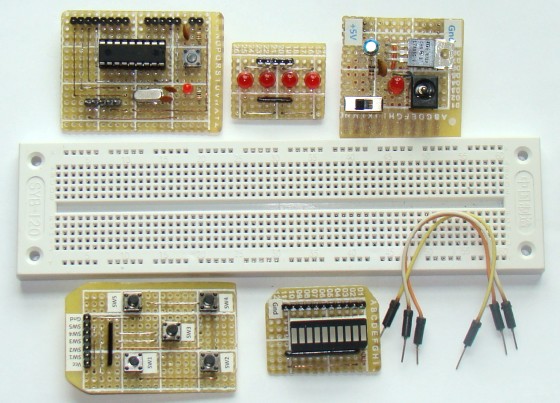
DIY plug-in modules to make microcontroller breadboarding easier
|
|
Breadboards are a great tool for prototyping and testing electronics circuits. Here I am sharing with you some plug-in modules that I once made to make my breadboarding life easier. I have used these modules many times in the PIC experiments described in this blog. These modules serve very common functions that are required in most microcontroller circuits. Their use not only reduces the number of wire connections on breadboard, but also expedites prototyping and makes debugging of the circuit easier.

Plug-in modules for easy microcontroller breadboarding
I got inspired to make these modules after getting tired of putting together the same basic microcontroller setup, tact switches and LEDs on breadboard again and again for testing every new project. If you are in a similar situation you may consider building these modules.
MCU module
This module carries a 18-pin PIC microcontroller (PIC16F628A, PIC16F88, PIC16F1827, etc). The power supply pins and the I/O ports of the microcontroller are accessible through male headers that can be easily plugged into a breadboard for rapid prototyping. The headers are arranged in such a way that all I/O pins of a port are available together in a row. This reduces the time to find a specific port pin. This module frees up a lot of space on the breadboard since the oscillator, reset, and ICSP connections are already on board. More details on this module is described HERE.

MCU module for 18-pin PIC
Power Supply module
Microcontrollers and peripheral devices require electric power to operate. This module provides a regulated +5 V power supply for your circuit on the breadboard. The +5 V and Ground terminals are accessible through male headers that easily go into the breadboard. The module uses the popular LM7805 voltage regulator IC. More details can be found HERE.

Tact switch, LED, and MAX232 modules
These are accessory modules that are frequently used in microcontroller circuits. LEDs are useful for checking the logic status of the output port, whereas tact switches can provide digital inputs. Sometimes, you may need to interface your project with a PC. Serial port communication is a good choice for doing that as it is easy to implement. However, you need a voltage translator to interface the TTL outputs from your microcontroller with a RS232 port of your PC. MAX232 IC serves this purpose very well with a few external capacitors for the internal charge pumps. The circuit diagram of these modules are pretty standard and I didn’t feel it necessary to provide here.

Accessory modules: Tact switches, LEDs, LED bargraph, MAX232
Seven segment LED display module
Seven segment LEDs are primarily used to display decimal numbers but they can also display a few alphabets and other characters. This module contains a 4-digit common cathode seven segment LED display, four NPN transistors for digit selection, and eight current limiting resistors for LED segments (a, b, c, d, e, f, g, DP). This module provides access to its LED segments and digit select pins through female headers. However, they can be replaced with male headers to make it plug-gable into the breadboard. The module uses a standard four digit multiplexed seven segment display circuit.

4-digit seven segment LED display module
Example project
Constructing these little modules is a one-time hard work, and prototyping becomes lot easier after that. The picture below shows a very simple temperature bargraph project setup on a breadboard using these modules. The PIC16F1827 microcontroller reads the analog output from a LM34DZ sensor, and displays the temperature on a 10-segment LED bargraph. The LED segments of the bargraph display are driven by RB0-RB7 and RA1-RA2 port pins, whereas the temperature sensor output is connected to RA0/AN0 ADC channel.The LED bargraph is labeled to display temperature ranging from 68-86 °F in a step of 2 °F. Seven jumper wires are sufficient to connect the modules together and complete this circuit on a breadboard.

Temperature bargraph circuit setup

Temperature displayed on 10-segment LED bargraph

Bottom side view of the boards (Click to enlarge)
|
|
I wanted to see if there any lab projects for building bridges, robots and many others from this URL. Can you help?
Pingback: DIY Plugins for Microcontroller Breadboarding | HACKOLOG - Amazing Hacks and Mods
When can we expect the tutorials and Kits to be available??? I’d really like to see each of these as Kits.. This would be great additions to our Build night at the local Hackerspace!!!!
Hey Charlie,
I am working on making PCBs of some of these kits. They will be available soon.
Very nice idea! for those tired of redoing the same modules over and over again.
For power supply I like solution like this: http://www.artekit.eu/products/accessories/ak-power
Paulo.
Pingback: DIY Nokia 3310 LCD breakout for embedded experiments | CircuitsDIY
Pingback: Nokia 3310 LCD breakout for embedded experiments | Circuits DIY
Good job. I’ve done something similar for 7-seg displays, the MAX232, and GLCDs. I really like the way you’ve pushed the pins through on the berg strips, yet retaining the plastic part to hold them in alignment. Never though of that. 😀
Thanks, Rohit! And I liked your way of SMT soldering using a toaster oven, very cool!
Excelent…
other modules can be a LCD and GLDC with conecction i2c
Keep up the good work, this site is really cool and never seems to fail with something useful every time I visit it.
Pingback: DIY breadboard modules for easy prototyping - Free Plans, Hacks, Howto's and other DIY stuff - Free Plans Online
Great work, and great writeup! Thanks for posting. Got here via hack-a-day
Amazing ideas I have been using breadboards for years an this never crossed my febile mind. this will cut hours off prototyping and worries about poor contacts or shorts. brilliant. I you also use “prefboad stitching” with wire wrap wire. I love that technique. It makes for a quick PCB. I built a 320 channel light controller with 40 flip flops using wire stitching it is still going strong after five years.
Pingback: DIY breadboard modules for easy prototyping | You've been blogged!
Pingback: Electronics-Lab.com Blog » Blog Archive » Breadboard modules for rapid prototyping of microcontroller projects
Good job! A while back I also found myself recreating the same bits and pieces over and over again and created some of these building blocks. I posted a button pad (http://diy.viktak.com/2011/02/buttons-for-digital-projects.html), a LED strip (http://diy.viktak.com/2011/02/led-strip.html), and a 6 digit 7 segment unit (http://diy.viktak.com/2011/02/6-digit-display-module.html) on my blog. I also created (though didn’t bother posting about them) a few more ones: a DS1307 based RTC module, a TTL to RS232 converter modul and some misc items that most people would not use.
Good write up!
vitya,
Your boards are really cool.
I saw this on Hackaday.com. I like the idea of these modules. I bought a Sparkfun 5V breadboard regulator and I use it all the time. But I didn’t really learn anything when I built that kit. I think you’ve got some good potential for teaching people the basics of soldering and the concepts behind the commonly used circuits. Good work, well done! 🙂
Pingback: DIY module breadboard pentru realizarea de prototipuri u?oar? | ro-Stire
Pingback: DIY breadboard modules for easy prototyping - Hack a Day