Atmega8 measures ambient temperature and relative humidity using HSM-20G sensor
|
|
In one of my previous posts, I discussed about Sensirion’s SHT11 and SHT75 sensors, which are capable of measuring both temperature and relative humidity. They are digital sensors and provide fully calibrated digital outputs for temperature and relative humidity. I also illustrated how to interface those sensors with a PIC microcontroller. Shawon Shahryiar from Dhaka, Bangladesh shared this project with us where he describes a method of interfacing the HSM-20G sensor to Atmega8 for measuring the ambient temperature and relative humidity. Unlike Sensirion’s SHT series, this is an analog sensor that converts the two ambient parameters into standard output voltages.

Using HSM-20G sensor with Atmega8
Shawon writes,
The materials used for the project are a ATMega8A micro, a HSM-20G analog relative humidity and temperature sensor module and my own-made 28 pin AVR development board along with some passive components. MikroC for AVR 5.00 compiler was used for coding.
Link for HSM-20G datasheet:
http://www.justmystage.com?/home/bellseki/HSM-20G.pdf.
HSM-20G is an analog sensor module unlike SHT75 or SHT21. If you go through the datasheet of HSM-20G, you will find out that they have given output voltage data from the humidity sensor for certain relative humidity values and they have plotted a graph too. What I did is simply used those data to plot and check if their graph is valid or fake. Now as you may notice the plot is not linear but rather has curve-like nature. Thus I used MATLAB’s “polyfit” function to get a equation for the plotted curve to the third degree. The reasons for using a third degree equation are firstly AVR has a built-in hardware multiplier that works pretty fast and secondly I won’t be using the micro to do any other tasks rather than metering. This is enough for a fairly good precision. A second degree is not that good enough while a higher order equation is unnecessary. If you you go through my program, you will see the equation under the function “read_humidity()”. The micro computes the data it gets from the HSM-20G module for relative humidity and determines what it should show.

Calibration curve for humidity sensor
The same task I did for temperature measurement but finding its data was a little cumbersome. If you see the datasheet for the module, you will notice they have given a circuit for interfacing the module to other peripherals like a micro or a multimeter and I used that circuit. However since they don’t know what value of resistance the user will use at the temperature circuit side and because it’s a thermistor built inside rather than semiconductor type sensor, they have provided resistance values rather than output voltages at various temperatures. Therefore and since I used their circuit, I calculated the voltages at different temperatures from their data. Again I used the voltage and temperature data as I did for the relative humidity part.

Calibration curve for temperature sensor
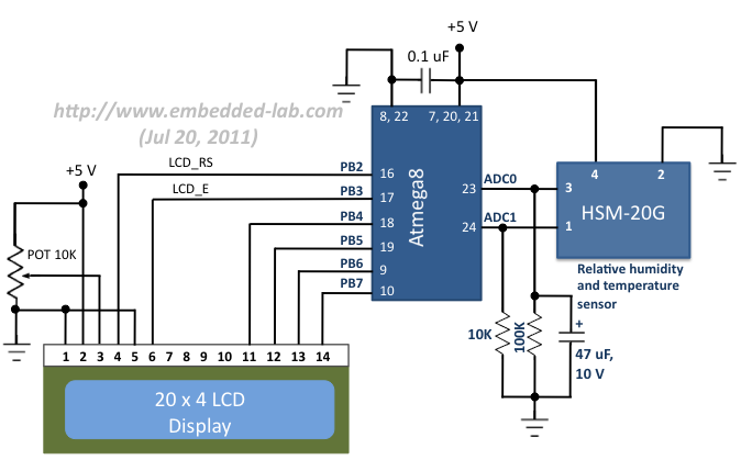
Circuit diagram
The circuit diagram is pretty simple. The two ADC channels (ADC0 and ADC1) of Atmega8 are used to measure the sensor output voltages that correspond to the ambient temperature and relative humidity. The two resistors and a capacitor connected to the output lines of the HSM-20G sensor are recommended in its datasheet. The results are displayed in a 4×20 character LCD.

Circuit diagram for interfacing HSM-20G to Atmega8

Circuit setup with the sensor module on the breadboard
Software
The firmware for this project is developed with MikroC Pro for AVR 5.00 compiler. The program is very simple and straight. There are six function other than the main function. These are described below briefly:
1. void setup_MCU() This function setups the micros peripherals for optimum operation by setting up individual buil-in peripheral registers and library function of the MikroC for AVR compiler. In this case the ADC and LCD libraries are used.
2. void display_common() This function simply displays the texts “Temperature” and “Relative Humidity” along with their units. Since there is only one screen, it’s called only once.
3. float read_voltage(unsigned short channel) This function read the ADC channel specified to it and takes the average of 64 ADC samples. This helps to reduce noisy A/D inputs and enhance precision. The result after doing all the maths is returned to the calling function.
4. float read_humidity() and float read_temperature() These compute relative humidity and temperature data using their equations and ADC data, and prepare for display.
5. void display_data(unsigned char x, unsigned char y, float value) This function specifies the location of the display and what to show from the acquired data.
Download the source code and HEX files of this project

Relative humidity and temperature are displayed on the LCD
| Many thanks to Shawon Shahryiar for contributing this project to Embedded Lab. He works as an Engineer in the Research and Development Cell at ELECTRO Group in Dhaka, Bangladesh.
Contact him at: |
 |

|
|
sir/mam can u please give me code in mikro c for avr using dht11 with atmega32.
thank you
i want the source bascam and c of the project humidity and temprature with avr?
can anyone help me?
So much thanks for such a good ccts realy I want to appreciate you and know how can I get more informatoins about these ccts? and is it possible or no?
best regards Mehdi
Very nice woke. people will get help from your job. many many thanks for the contribution. Go ahead. we wish you at the best.
Thank you for such a nice post….things are very interesting and clear in the tutorial
with regards,
milind
thank you and i hope life happy for you
Pingback: Electronics-Lab.com Blog » Blog Archive » Atmega8 + HSM-20G to measure the relative humidity and temperature