AVR XMEGA tutorials
These introductory and comprehensive tutorials on AVR XMEGA microcontrollers are contributed by Shawon Shahryiar, a technologist, hardware maker, educator and EE graduate from Ahsanullah University of Science and Technology, Dhaka.
The XMega series is a powerful addition to the existing arsenal of Atmel’s AVR-core micros. As much as I have personally studied about it so far and felt, the XMega series incorporates many features of conventional 32-bit ARM micros like alternate I/O pin mapping functionalities, sophisticated clock options and data buses, multiple communication platforms that have several uses, variety of capture-PWM options, 12-bit ADCs and DACs, DMA controller, USB hardware, etc.
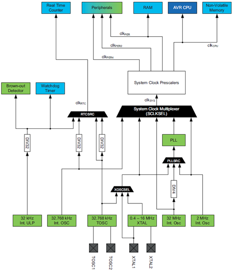
There are several clock sources that XMega micros can use as clock. These are both internal and external clock sources. As stated earlier, clocks are not set by fuse settings unlike traditional Mega AVRs, they are controlled by software and the outputs from these sources can be multiplied using the internal Phase Locked-Loop (PLL)..
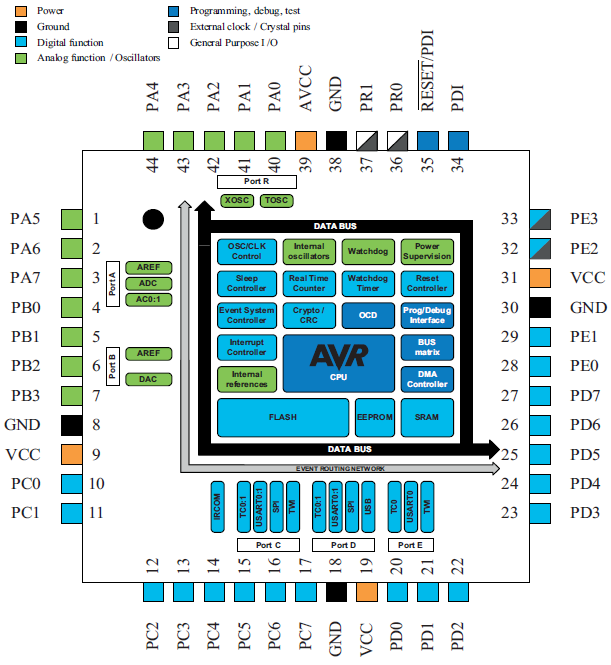
Any microcontroller must have I/O pins for taking inputs and providing outputs. The ATXMega32A4U just like any other micro has 34 programmable I/O pins divided unevenly amongst six IO ports. Most I/O ports are 8 bit wide. XMega I/Os have digital, analog and special purpose functions. Some I/O pins have more than one use. A quick view of the XMega I/O pins reveals the purpose of these pins.
|
|
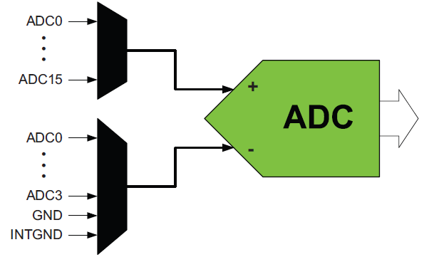
Unlike the ADCs of other microcontroller the ADC of XMega devices is a highly complex tool. The level of complexity is so much that without understanding every bits-and-pieces of this piece of hardware a user won’t enjoy its absolute power. XMega ADC is also the most confusing hardware as it is not like other MCU ADCs.
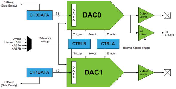
XMega micros are equipped with 12 bit fast DACs apart from PWM blocks and again it proves itself to be a very versatile family of microcontrollers. In this post we will have a look into this block.
External interrupts are a must have feature in any microcontroller. Interrupts solve a lot of problem that would have otherwise been dependent on polling methods. For instance when we press the volume up key of a TV tuner’s remote controller, the remote controller quickly responds by transmitting the volume up command to the TV set and in turn the TV’s volume increases.
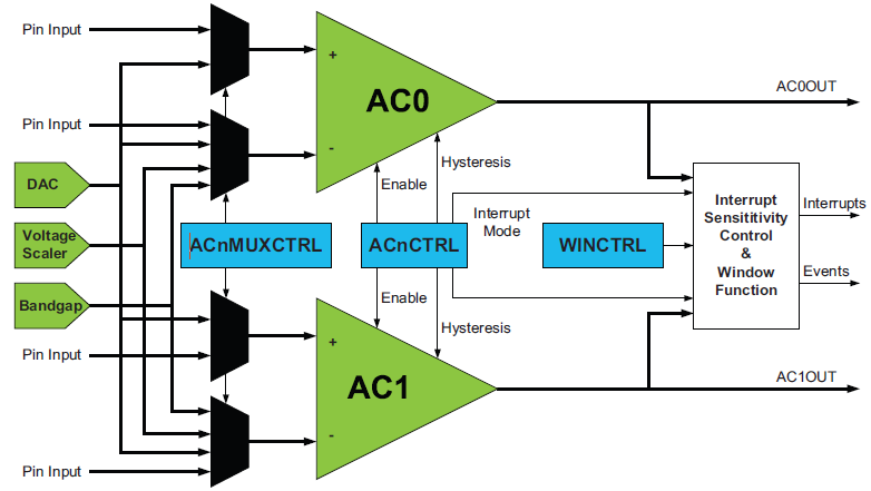
The XMega family of micros come loaded with high performance dual analog comparator modules. However so far we saw that between the traditional 8-bit micros and the XMega micros, the major difference apart from programming is the overall nifty enhancements in all common hardware blocks. When it comes to the analog comparators of the XMega micros, the same is true. In this issue we will explore the XMega analog comparator block.


Hi, Could you tell me if the LCD driver within the XMEGA128B3 can be operated with only 2 comm lines? If it can, will I still be able to use the ascii character arrangement within the device to drive a bespoke monochrome LCD with two common terminals and 14 segments?
Very meny thanks for your help.
Hi. Can you give me reference book to code ATXMEGA? and basic header code?
Pic microcontroler
Hi there!
Have you tried to work with an SPI or UART coms?
Hi there!! Please, Could you share the libraries IO.H and CLOCK.H?
Thank U so Much
hi
can you please tell me what software do you use for simulating xmega?
Hi Shawon
I am a hobbyist and would like to know are your header files for xmega available or is it only for in-house use?
Kind regards
Anton
Hi,
For every post there’s a header for that specific hardware block. I’ve shared the headers with the posts but I don’t understand your point. What did you mean by in-house use?
Thanks.