XMega Analog Comparator
|
|
Previously we dealt with the XMega Analog-to-Digital Converter (ADC) block. We know that we can use the ADC to measure voltages and take decisions based on voltage values/levels but sometimes it is enough to detect voltage levels and not to measure the exact voltage values. In such occasions where we just need to check voltage levels relative to a reference or threshold value, we need an Analog Comparator (AC). An analog comparator can be used to compare two voltage levels and based on that it can be used to generate a logic output (0 or 1) to indicate which of the two levels is higher or lower than the other. That’s all and there isn’t much about analog comparators. The XMega family of micros come loaded with high performance dual analog comparator modules. However so far we saw that between the traditional 8-bit micros and the XMega micros, the major difference apart from programming is the overall nifty enhancements in all common hardware blocks. When it comes to the analog comparators of the XMega micros, the same is true. In this issue we will explore the XMega analog comparator block.
A Brief Overview
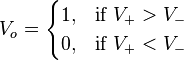
Generally a comparator is a device that compares two quantities. Analog comparators compare voltage – an analog quantity. An analog comparator is essentially an op-amp with infinite gain. It has one output and two inputs. The output is switched to VDD or ground (0V) depending on the relative voltage levels in the two input pins. Just as with an op-amp the two inputs are labeled as inverting input (INV) and non-inverting input (NINV). When the non-inverting input voltage is higher than that of the inverting input, the output switches to VDD and when it is the other way, the output switches to ground. Thus we get two logic states.
In the XMega micros, the basic comparator that one may find in a typical 8-bit micro is enhanced a bit. The basic operations are same but additionally a few features have been included. For instance we can add hysteresis and can change operational speed of these comparators by altering propagation delays. Hysteresis is useful feedback mechanism for fast varying input signals (especially ringing/oscillating signals) that cause high rates of output swings. By adding hysteresis to a comparator we can effectively reduce the frequent oscillation of the output.

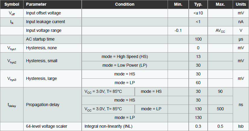
In the ATXMega micros, two levels of hysteresis can be programmed – small (30mV) and large (60mV). The datasheet documents of the XMega devices state these values and much more. As the name suggests High Speed mode yields in faster operation while the default Low Power mode is slower than the former but it is much more energy efficient. Shown below is the table for electrical specs of the ATXMega32A4U’s analog comparator module. Check it out:
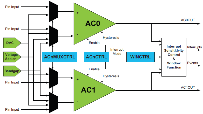
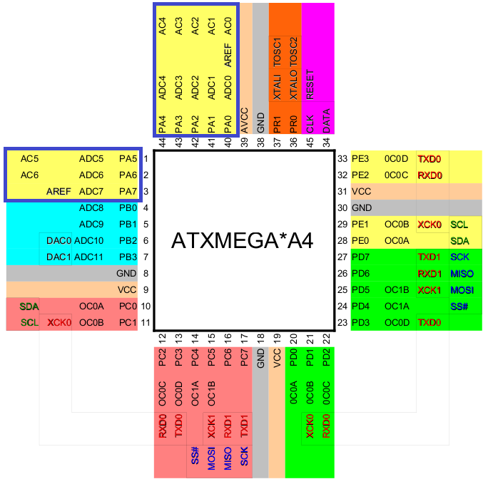
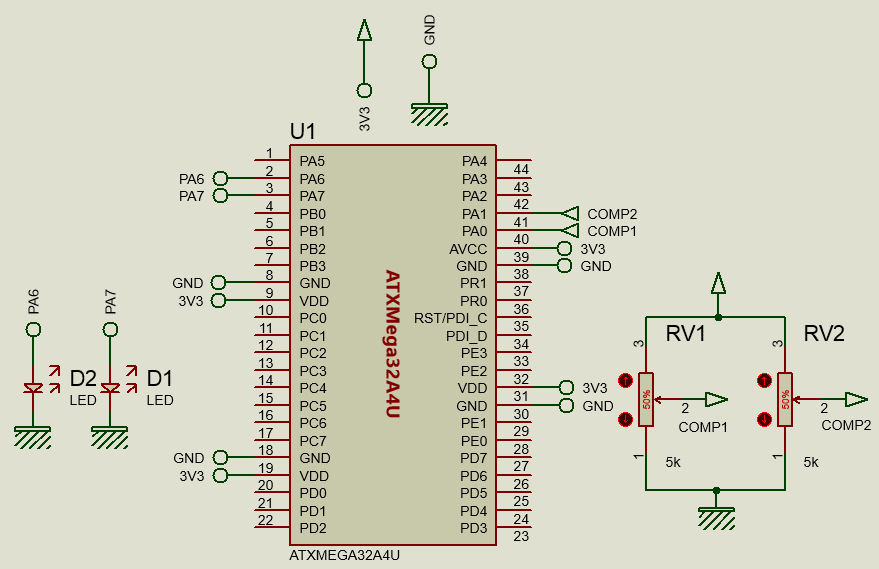
Unlike old school micros, the input pins to the comparators are not tied to a specific set of I/O pins of an I/O port. We can literally use any pin of a port that is related to the comparator block. I have used an ATXMega32A4U micro for this issue. This micro has a pair of analog comparators under a single comparator block called Analog Comparator A (ACA). Larger XMega devices have more of such comparator blocks. Each block has a pair of comparator modules. Each comparator in a block has a unique designation like ACA.AC0, meaning the first analog comparator of block A comparator pair attached with PORTA. I/Os related to ACA are available to PORTA pins only. Watch the blue boxes in the image below:
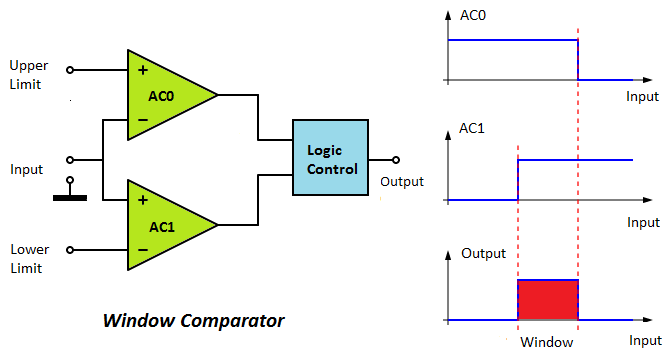
We can also set a pair of comparators as a window comparator. Window comparators are also known as limit comparators because of their limit sensing ability. Such comparators determine when the input voltage to it is within a preselected range. There are two voltage limit values (upper limit and lower limit) or references for an input signal that define the boundaries of the voltage window. An input can be within, outside, above or below the predefined window and so there are four states.
Window comparators have several applications. One good application is a battery charger. A window comparator will always monitor the voltage level of a battery with respect to references and based on the four aforementioned output conditions, charging can be started or stopped automatically without needing much coding and attention.
Three internal reference sources can be tied with the comparator pins. These are as follows:
- Bandgap voltage source or precise 1.0V internal source
- DAC output
- 64-step scalable VDD
Having these sources frees us from adding and implementing additional hardware for reference sources.
Comparator events can also generate interrupt requests as well as trigger the XMega event system. Using these we can use can get critical statuses quickly without much intervention of the CPU.
Registers
The table below shows the registers associated with analog comparator block:

The registers and individual bits speak of themselves. Multiplexer control registers, ACnMUXCTRL are what we use code to select input pins. Analog comparator control registers, ACnCTRL are coded to setup interrupt levels and modes of interrupt. ACnCTRL registers are also programmed to select hysteresis and operating speed/power. A status register keeps track of comparator-related events. This register comes to no use if we take comparator outputs directly from port pins or if its bit states are not needed to be read. There is also a dedicated register for window mode operation. It is used to configure everything necessary for window comparator mode operation. CTRLA register enables physical comparator output pins. With the CTRLB register we can program the scalable VDD reference. I’ll discuss more on this register in a later part of this doc. Lastly regarding the last two registers which are related to constant current source, I haven’t been able to test the constant current source capability of the XMega micros as no such registers exists for the ATXMega32A4U.
Coding
The code examples I showed in this issue are very simple to understand. Except the code example for the window comparator demo, the outputs from the comparators are directly taken from their respective I/O port pins (PORTA.6 and PORTA.7). LEDs are used to visualize output states. To keep things easy I didn’t use any interrupt in any of my codes. However interrupts can be easily implemented with these examples with minor changes. 8MHz clock is derived from the internal 32MHz oscillator after proper scaling and with this clock the XMega runs.
Basic Single Analog Comparator
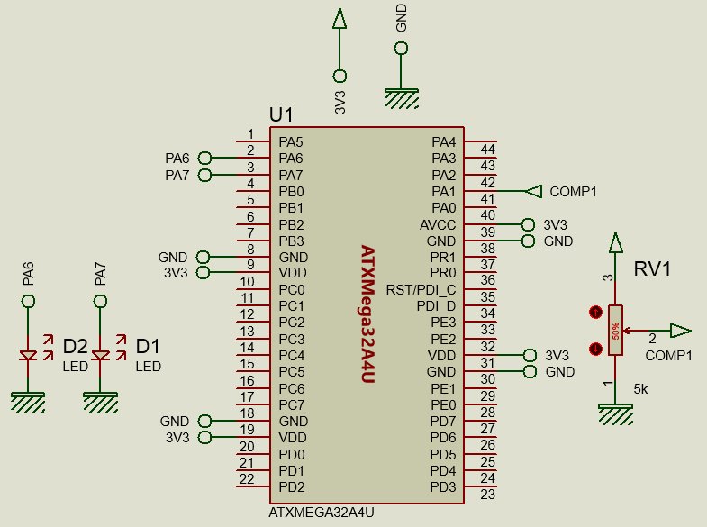
The basic comparator is well explained in the beginning of this issue. I’m not going to repeat the same old literature. GPIO pins PORTA.0 and PORTA.1 are the positive pin and the negative pin to the analog comparator ACA.AC0 respectively. GPIO pin PORTA.7 is the output of ACA.AC0 and this pin is connected to a LED. Check the simplified connection diagram below:
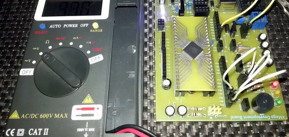
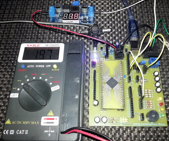
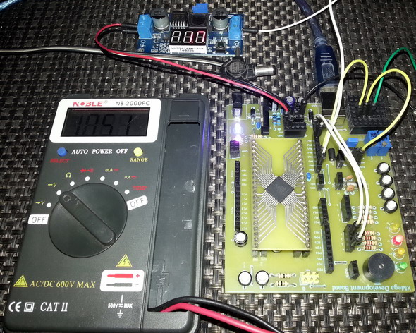
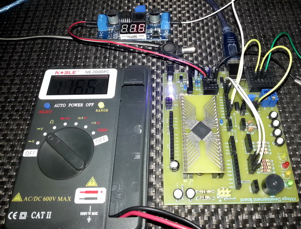
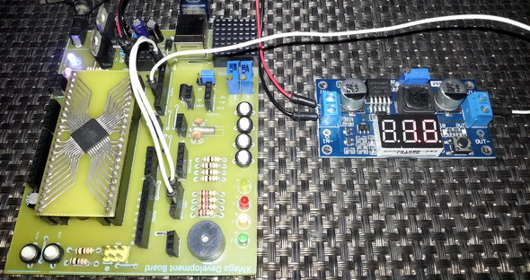
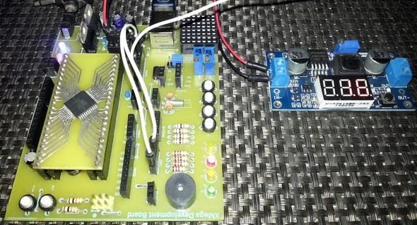
In the practical demo, I tied the negative pin to a 1.9V source and varied the voltage on the positive pin. Check the code example, photos and the videos:
#include "CLOCK.h"
#include "IO.h"
#include "AC.h"
void setup();
void setup_clock();
void setup_GPIO();
void setup_AC();
void main()
{
setup();
while(1)
{
};
}
void setup()
{
setup_clock();
setup_GPIO();
setup_AC();
}
void setup_clock()
{
asm cli;
OSC_CTRL |= OSC_RC32KEN_bm;
while(!(OSC_STATUS & OSC_RC32KRDY_bm));
OSC_CTRL |= OSC_RC32MEN_bm;
CPU_CCP = CCP_IOREG_gc;
CLK_PSCTRL = ((CLK_PSCTRL & (~(CLK_PSADIV_gm | CLK_PSBCDIV1_bm
| CLK_PSBCDIV0_bm))) | CLK_PSADIV_1_gc | CLK_PSBCDIV_2_2_gc);
OSC_DFLLCTRL = ((OSC_DFLLCTRL & (~(OSC_RC32MCREF_gm | OSC_RC2MCREF_bm))) |
OSC_RC32MCREF_RC32K_gc);
DFLLRC32M_CTRL |= DFLL_ENABLE_bm;
while(!(OSC_STATUS & OSC_RC32MRDY_bm));
CPU_CCP = CCP_IOREG_gc;
CLK_CTRL = ((CLK_CTRL & (~CLK_SCLKSEL_gm)) | CLK_SCLKSEL_RC32M_gc);
OSC_CTRL &= (~(OSC_RC2MEN_bm | OSC_XOSCEN_bm | OSC_PLLEN_bm));
PORTCFG_CLKEVOUT = 0x00;
}
void setup_GPIO()
{
PORTA_OUT = 0x00;
PORTA_DIR = 0x80;
PORTCFG_MPCMASK = 0xFF;
PORTA_PIN4CTRL = (PORT_OPC_TOTEM_gc | PORT_ISC_BOTHEDGES_gc);
PORTA_INTCTRL = ((PORTA_INTCTRL & (~(PORT_INT1LVL_gm | PORT_INT0LVL_gm))) |
PORT_INT1LVL_OFF_gc | PORT_INT0LVL_OFF_gc);
}
void setup_AC()
{
ACA_WINCTRL = 0x00;
ACA_AC0MUXCTRL = (AC_MUXPOS_PIN0_gc | AC_MUXNEG_PIN1_gc);
ACA_AC0CTRL = (AC_INTMODE_BOTHEDGES_gc | AC_INTLVL_OFF_gc | (0 << AC_HSMODE_bp)
| AC_HYSMODE_NO_gc | (1 << AC_ENABLE_bp));
ACA_AC1MUXCTRL = 0x00;
ACA_AC1CTRL = 0x00;
ACA_CTRLA = ((0 << AC_AC1OUT_bp) | (1 << AC_AC0OUT_bp));
}

Video link: https://www.youtube.com/watch?v=jS9-tasyTGI.
Dual Independent Analog Comparators
This example is basically the same as the previous one except this time both comparators of the ACA block are used and both are operated in high speed mode. ACA.AC0’s and ACA.AC1’s negative inputs are fed to the 64-step scalable VDD reference source and the bandgap voltage (precise 1.0V) reference source respectively. The positive inputs connected to PORTA.0 and PORTA.1 pins are compared with these internal sources. Since the comparators do not share any common input, they are independent of each other.
In my discussion with the registers related to the analog comparator, I skipped the ACA_CTRLB register. Now we will see its use. We can program this register to get desired voltage from the 64-step scalable VDD reference source according to the formula:
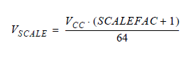
In my example I coded the 64-step scalable VDD reference source to provide an output of 1.65V, which is roughly the half of the VDD. In the code example, you’ll notice the line:
ACA_CTRLB = 0x1F;
Thus the scale factor is 31 (0x1F) and the scaled VDD is half of the VCC. Since VCC/VDD is 3.3V, the scaled voltage is 1.65V.
#include "CLOCK.h"
#include "IO.h"
#include "AC.h"
void setup();
void setup_clock();
void setup_GPIO();
void setup_AC();
void main()
{
setup();
while(1);
}
void setup()
{
setup_clock();
setup_GPIO();
setup_AC();
}
void setup_clock()
{
asm cli;
OSC_CTRL |= OSC_RC32KEN_bm;
while(!(OSC_STATUS & OSC_RC32KRDY_bm));
OSC_CTRL |= OSC_RC32MEN_bm;
CPU_CCP = CCP_IOREG_gc;
CLK_PSCTRL = ((CLK_PSCTRL & (~(CLK_PSADIV_gm | CLK_PSBCDIV1_bm
| CLK_PSBCDIV0_bm))) | CLK_PSADIV_1_gc | CLK_PSBCDIV_2_2_gc);
OSC_DFLLCTRL = ((OSC_DFLLCTRL & (~(OSC_RC32MCREF_gm | OSC_RC2MCREF_bm))) |
OSC_RC32MCREF_RC32K_gc);
DFLLRC32M_CTRL |= DFLL_ENABLE_bm;
while(!(OSC_STATUS & OSC_RC32MRDY_bm));
CPU_CCP = CCP_IOREG_gc;
CLK_CTRL = ((CLK_CTRL & (~CLK_SCLKSEL_gm)) | CLK_SCLKSEL_RC32M_gc);
OSC_CTRL &= (~(OSC_RC2MEN_bm | OSC_XOSCEN_bm | OSC_PLLEN_bm));
PORTCFG_CLKEVOUT = 0x00;
}
void setup_GPIO()
{
PORTA_OUT = 0x00;
PORTA_DIR = 0xC0;
PORTCFG_MPCMASK = 0xFF;
PORTA_PIN4CTRL = (PORT_OPC_TOTEM_gc | PORT_ISC_BOTHEDGES_gc);
PORTA_INTCTRL = ((PORTA_INTCTRL & (~(PORT_INT1LVL_gm | PORT_INT0LVL_gm))) |
PORT_INT1LVL_OFF_gc | PORT_INT0LVL_OFF_gc);
}
void setup_AC()
{
unsigned char regval = 0;
regval = (AC_INTMODE_BOTHEDGES_gc | AC_INTLVL_OFF_gc | (1 << AC_HSMODE_bp)
| AC_HYSMODE_NO_gc | (1 << AC_ENABLE_bp));
ACA_AC0MUXCTRL = (AC_MUXPOS_PIN0_gc | AC_MUXNEG_SCALER_gc);
ACA_AC0CTRL = regval;
ACA_AC1MUXCTRL = (AC_MUXPOS_PIN1_gc | AC_MUXNEG_BANDGAP_gc);
ACA_AC1CTRL = regval;
ACA_WINCTRL = 0x00;
ACA_CTRLA = ((1 << AC_AC1OUT_bp) | (1 << AC_AC0OUT_bp));
ACA_CTRLB = 0x1F;
}

Video link: https://www.youtube.com/watch?v=emOd4qec0hg.
Window Mode Comparator
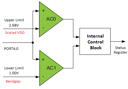
The window mode comparator’s setups are similar to those of the previous example but this time there’s only one positive input instead of two and so both comparators share the same positive input. Just as in previous example, I used the same internal voltage reference sources with the negative inputs. The internal diagram should look like this:
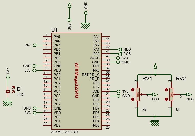
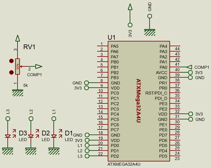
Check the schematic:
From the above schematic and block diagram we can realize that:
- Upper limit = 2.68V
- Lower limit = 1.00V
- The window is in between 1.00V to 2.68V.
- L1 = Red LED, L2 = Yellow LED and L3 = Green LED
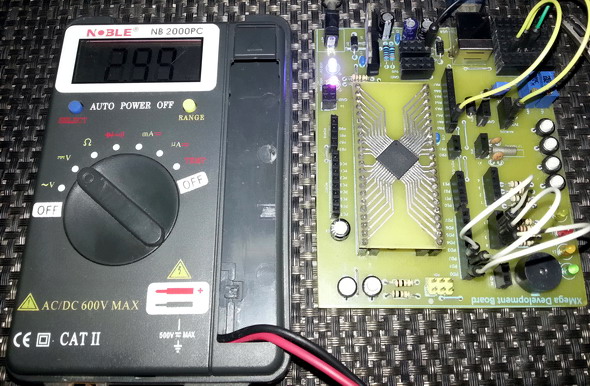
When the input (PORTA.0 pin) is less than 1.00V, L1 lights only, indicating below window condition. Similarly when the input is greater than 2.68V, L3 lights up, indicating above window condition. When the input is between these two extremes, L2 lights alone, indicating inside window condition. During transitions between levels, two LEDs may appear to light up simultaneously and well it is just because of intermediate states. For more understanding check the video out.
#include "CLOCK.h"
#include "IO.h"
#include "AC.h"
void setup();
void setup_clock();
void setup_GPIO();
void setup_AC();
void main()
{
unsigned char result = 0;
setup();
while(1)
{
result = (ACA_STATUS & 0xC0);
if(result == AC_WSTATE_ABOVE_gc)
{
PORTD_OUT = 0x01;
}
if(result == AC_WSTATE_INSIDE_gc)
{
PORTD_OUT = 0x02;
}
if(result == AC_WSTATE_BELOW_gc)
{
PORTD_OUT = 0x04;
}
};
}
void setup()
{
setup_clock();
setup_GPIO();
setup_AC();
}
void setup_clock()
{
asm cli;
OSC_CTRL |= OSC_RC32KEN_bm;
while(!(OSC_STATUS & OSC_RC32KRDY_bm));
OSC_CTRL |= OSC_RC32MEN_bm;
CPU_CCP = CCP_IOREG_gc;
CLK_PSCTRL = ((CLK_PSCTRL & (~(CLK_PSADIV_gm | CLK_PSBCDIV1_bm
| CLK_PSBCDIV0_bm))) | CLK_PSADIV_1_gc | CLK_PSBCDIV_2_2_gc);
OSC_DFLLCTRL = ((OSC_DFLLCTRL & (~(OSC_RC32MCREF_gm | OSC_RC2MCREF_bm))) |
OSC_RC32MCREF_RC32K_gc);
DFLLRC32M_CTRL |= DFLL_ENABLE_bm;
while(!(OSC_STATUS & OSC_RC32MRDY_bm));
CPU_CCP = CCP_IOREG_gc;
CLK_CTRL = ((CLK_CTRL & (~CLK_SCLKSEL_gm)) | CLK_SCLKSEL_RC32M_gc);
OSC_CTRL &= (~(OSC_RC2MEN_bm | OSC_XOSCEN_bm | OSC_PLLEN_bm));
PORTCFG_CLKEVOUT = 0x00;
}
void setup_GPIO()
{
PORTA_OUT = 0x00;
PORTA_DIR = 0xC0;
PORTCFG_MPCMASK = 0xFF;
PORTA_PIN4CTRL = (PORT_OPC_TOTEM_gc | PORT_ISC_BOTHEDGES_gc);
PORTA_INTCTRL = ((PORTA_INTCTRL & (~(PORT_INT1LVL_gm | PORT_INT0LVL_gm))) |
PORT_INT1LVL_OFF_gc | PORT_INT0LVL_OFF_gc);
PORTD_OUT = 0x00;
PORTD_DIR = 0x0F;
PORTCFG_MPCMASK = 0xFF;
PORTD_PIN6CTRL = (PORT_OPC_TOTEM_gc | PORT_ISC_BOTHEDGES_gc);
PORTD_INTCTRL = ((PORTD_INTCTRL & (~(PORT_INT1LVL_gm | PORT_INT0LVL_gm))) |
PORT_INT1LVL_OFF_gc | PORT_INT0LVL_OFF_gc);
}
void setup_AC()
{
unsigned char reg_val = 0;
reg_val = (AC_INTMODE_BOTHEDGES_gc | AC_INTLVL_OFF_gc | (0 << AC_HSMODE_bp)
| AC_HYSMODE_LARGE_gc | (1 << AC_ENABLE_bp));
ACA_AC0MUXCTRL = (AC_MUXPOS_PIN0_gc | AC_MUXNEG_SCALER_gc);
ACA_AC0CTRL = reg_val;
ACA_AC1MUXCTRL = (AC_MUXPOS_PIN0_gc | AC_MUXNEG_BANDGAP_gc);
ACA_AC1CTRL = reg_val;
ACA_WINCTRL = ((1 << AC_WEN_bp) | AC_WINTMODE_OUTSIDE_gc | AC_WINTLVL_OFF_gc);
ACA_CTRLA = (1 << AC_AC1OUT_bp) | (1 << AC_AC0OUT_bp);
ACA_CTRLB = 0x33;
}


Video link: https://www.youtube.com/watch?v=eQB8MUIlMdU.
Comparator Hysteresis Demo
Finally in this example, we will observe the effect of varying and applying hysteresis to a comparator. For this I configured both comparators with same input pins – PORTA.1 (+) and internal scaled VDD (-). Both comparators have the same settings. However one comparator has a large (60mV) hysteresis while the other has a small hysteresis (30mV). When the input is slowly varied around the point of tripping, it will be seen that the one with larger hysteresis will react less to the change than the other. This effect is specifically useful in noisy environments. Check the video clip carefully for better understanding.
#include "CLOCK.h"
#include "IO.h"
#include "AC.h"
void setup();
void setup_clock();
void setup_GPIO();
void setup_AC();
void main()
{
setup();
while(1)
{
};
}
void setup()
{
setup_clock();
setup_GPIO();
setup_AC();
}
void setup_clock()
{
asm cli;
OSC_CTRL |= OSC_RC32KEN_bm;
while(!(OSC_STATUS & OSC_RC32KRDY_bm));
OSC_CTRL |= OSC_RC32MEN_bm;
CPU_CCP = CCP_IOREG_gc;
CLK_PSCTRL = ((CLK_PSCTRL & (~(CLK_PSADIV_gm | CLK_PSBCDIV1_bm
| CLK_PSBCDIV0_bm))) | CLK_PSADIV_1_gc | CLK_PSBCDIV_2_2_gc);
OSC_DFLLCTRL = ((OSC_DFLLCTRL & (~(OSC_RC32MCREF_gm | OSC_RC2MCREF_bm))) |
OSC_RC32MCREF_RC32K_gc);
DFLLRC32M_CTRL |= DFLL_ENABLE_bm;
while(!(OSC_STATUS & OSC_RC32MRDY_bm));
CPU_CCP = CCP_IOREG_gc;
CLK_CTRL = ((CLK_CTRL & (~CLK_SCLKSEL_gm)) | CLK_SCLKSEL_RC32M_gc);
OSC_CTRL &= (~(OSC_RC2MEN_bm | OSC_XOSCEN_bm | OSC_PLLEN_bm));
PORTCFG_CLKEVOUT = 0x00;
}
void setup_GPIO()
{
PORTA_OUT = 0x00;
PORTA_DIR = 0xC0;
PORTCFG_MPCMASK = 0xFF;
PORTA_PIN4CTRL = (PORT_OPC_TOTEM_gc | PORT_ISC_BOTHEDGES_gc);
PORTA_INTCTRL = ((PORTA_INTCTRL & (~(PORT_INT1LVL_gm | PORT_INT0LVL_gm))) |
PORT_INT1LVL_OFF_gc | PORT_INT0LVL_OFF_gc);
PORTD_OUT = 0x00;
PORTD_DIR = 0x0F;
PORTCFG_MPCMASK = 0xFF;
PORTD_PIN6CTRL = (PORT_OPC_TOTEM_gc | PORT_ISC_BOTHEDGES_gc);
PORTD_INTCTRL = ((PORTD_INTCTRL & (~(PORT_INT1LVL_gm | PORT_INT0LVL_gm))) |
PORT_INT1LVL_OFF_gc | PORT_INT0LVL_OFF_gc);
}
void setup_AC()
{
unsigned char reg_val;
reg_val = (AC_MUXPOS_PIN1_gc | AC_MUXNEG_SCALER_gc);
ACA_AC0MUXCTRL = reg_val;
ACA_AC0CTRL = (AC_INTMODE_BOTHEDGES_gc | AC_INTLVL_OFF_gc | (1 << AC_HSMODE_bp)
| AC_HYSMODE_LARGE_gc | (1 << AC_ENABLE_bp));
ACA_AC1MUXCTRL = reg_val;
ACA_AC1CTRL = (AC_INTMODE_BOTHEDGES_gc | AC_INTLVL_OFF_gc | (1 << AC_HSMODE_bp)
| AC_HYSMODE_SMALL_gc | (1 << AC_ENABLE_bp));
ACA_CTRLA = (1 << AC_AC1OUT_bp) | (1 << AC_AC0OUT_bp);
ACA_CTRLB = 0x1F;
ACA_WINCTRL = 0x00;
}

Video link: https://www.youtube.com/watch?v=iLZgnKrzzv8.
Files:
XMega Comparator
References:
- XMega AU Manual and Datasheet
- Mikroelektronika’s Website (www. Mikroe.com).
Happy coding.
Author: Shawon M. Shahryiar
https://www.facebook.com/groups/microarena
https://www.facebook.com/MicroArena
+8801970046495
04.07.2015
|
|
Pingback: XMega Analog Comparator - Arduino collector blog