Rapid Development Board for PIC12F Series Microcontrollers
|
|
The 12F series of PIC microcontrollers are handy little 8-pin devices designed for small embedded applications that do not require too many I/O resources, and where small size is advantageous. These applications include a wide range of everyday products such as hair dryers, electric toothbrushes, rice cookers, vacuum cleaners, coffee makers, and blenders. Despite their small size, the PIC12F series microcontrollers offer many advanced features including wide operating voltage, internal programmable oscillator, 4 channels of 10-bit ADC, on-board EEPROM memory, on-chip voltage reference, multiple communication peripherals (UART, SPI, and I2C), PWM, and more. Today we are introducing a new development board (rapidPIC-08 V1.0) for easy and rapid prototyping of standalone applications using PIC12F microcontrollers.
Rapid PIC12F Series Microcontroller Development Board
Features:
- On-board voltage regulator provides 5 V supply for your application circuit
- Header pins to access all six I/O pins of PIC12F microcontroller
- On-board Reset and ICSP programming header
- ON/OFF slide switch
- Four tact switches with a voltage divider network on board for connecting to an analog pin
- On-board power indicator and digital output LEDs
- Board dimensions are 1.95″ X 3.9″ (5cm X 10cm)
Circuit Diagrams
The regulated +5V power supply voltage on board is derived using the AMS1117-5.0 regulator IC. The detail of the power supply unit (PSU) is shown below. The DC input should be in-between 7-12V. LD1 is a power-on indicator LED.
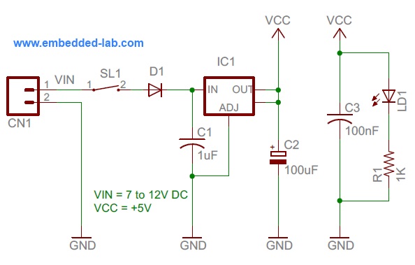
PSU Circuit
All microcontroller I/O pins and +5V power supply are accessed through header pins. A separate 5-pin header is provided for easy ICSP interface with the PICKit-2 or PICKit-3 programmer/debugger device.
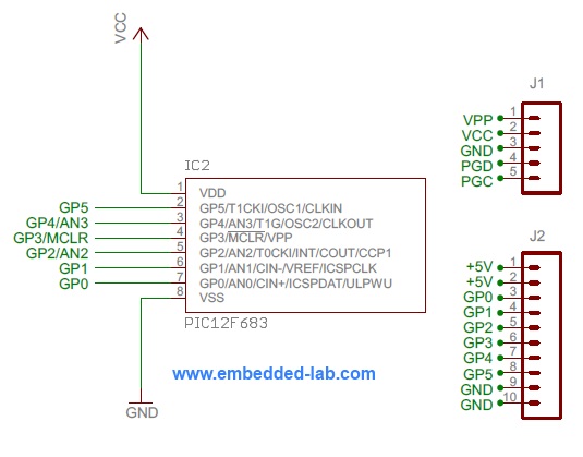
MCU and header connections
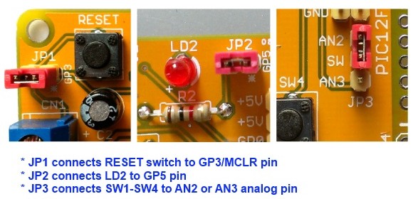
There are five tact switches for user inputs and one LED for output on the board. Out of five tact switches, one (SW5 in figure below) can be connected to the GP3/MCLR pin of the PIC12F microcontroller through a 2-pin jumper (JP1). So, this switch can be used as either Reset or digital input through GP3, based on the MCU configuration Word. It can be completely disconnected from the circuit by taking the jumper OFF. The remaining four tact switches (SW1 through SW4) are for digital inputs. In order to save I/O pins, they are interfaced to the PIC12F microcontroller through one analog input pin using a voltage divider network as shown in the circuit diagram below. Jumper JP3 can connect these switches to either AN2 or AN3 analog pin of the PIC12F microcontroller. If you want to use a different analog channel (other than AN2 and AN3), you can simply take the Jumper JP3 OFF and manually hook it to the analog pin of your choice. Visit my Connecting Multiple Switches to a Single I/O Pin article for more detail on the implementation this approach.
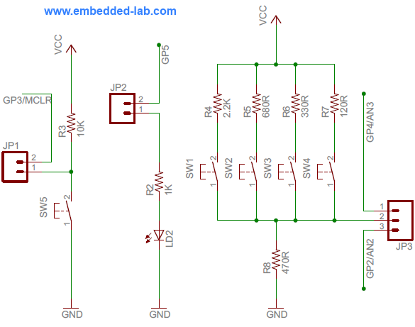
Tact switches and output LED
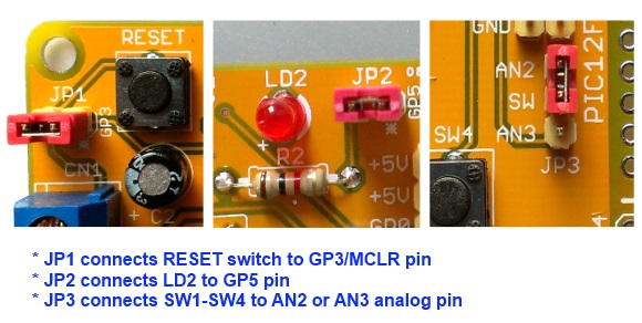
Jumper settings for Reset, output LED, and tact switches
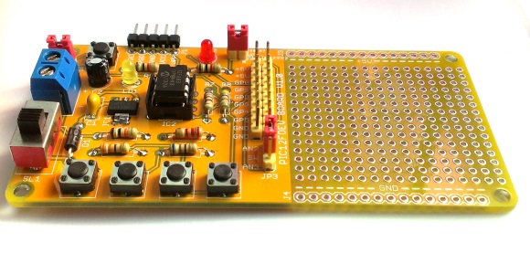
The rapiPIC-08 development board has an additional prototyping area on the right side for your application circuit.
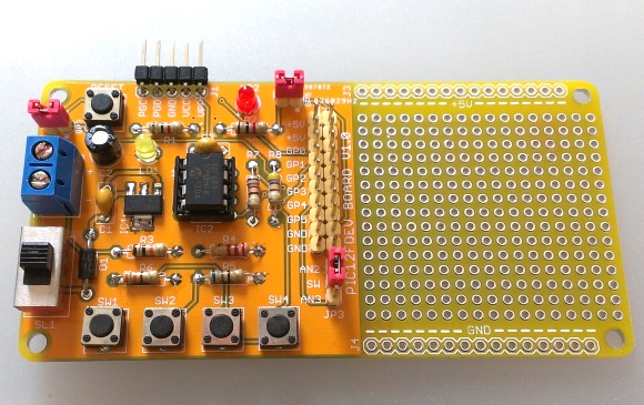
Assembled rapidPIC-08 development board
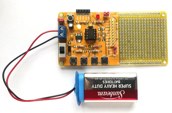
Powering rapidPIC-08 board through a 9V PP3 battery
Buy rapidPIC-08 Development Board as a kit
We are currently offering a DIY kit version of the rapidPIC-08 development board on Tindie for those who are interested. Check this out.
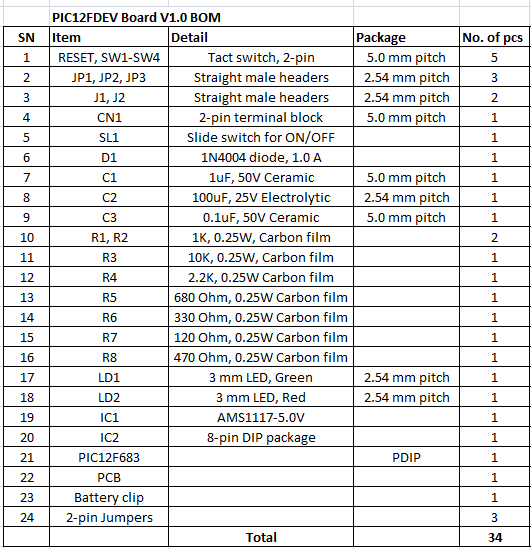
Items you will receive in the kit
PIC12F based projects
Wondering what you can do with this board? If you search online you will find tons of cool projects done with PIC12F microcontrollers. Here’s a list of few of them.
- A beginner’s data logger with serial interface
- 0-20V digital voltmeter
- Playing a song tune with PIC12F683
- Ultrasonic sound detector
- Metal detector
- PAL video superimposer
- Laser projector
- A super simple IR remote
- Thermometer with Nokia 3310 LCD
- Pong video game
- Mini servo controller
- Temperature sensing mug
- IR light dimmer
- Another Ping-Pong game
- Another metal detector
- Single-chip Audio Player
- Remote-controlled light dimmer
|
|
Hello, I am really interested to buy this PIC12F series development board. But I have a project using PIC12F1840 MCU’s. So, can I use this development board for testing PIC12F1840 MCU’s? Is it Compatible or its only for PIC12F683 MCU’s?
Our new PIC12F project board is available here:
https://www.tindie.com/products/rajbex/pic12f-series-microcontrollers-project-board-kit/
Yes, it is compatible with PIC12F1840.