Reviewing the iCA05 Graphic LCD development kit from iCircuit Technologies
|
|
The Graphical LCD (GLCD) displays provide more flexibility in presenting data, as compared to standard character-based LCDs. Owing to a significant drop in price lately, GLCDs have become more popular these days in the hackers’ and DIY worlds. If you are planning on doing an embedded microcontroller project including a graphical LCD display, you might be interested in this PIC-based GLCD development kit from iCircuit Technologies. This decently priced development kit will help you to get started quickly with your project. Here’s a brief review of the kit.

PIC-based GLCD development kit from iCircuit Technologies
This GLCD development kit includes a 28-pin PIC development board, a 128×64 GLCD module (KS0108 controller chip), a GLCD adapter board, two 10-pin IDC ribbon cables, and a blank prototyping board (see the picture below).

Complete kit
The basic circuits, such as regulated +5.0V/+3.3V power supply, reset switch, ICSP header, external crystal, etc., which are required to run a microcontroller, are all setup on the development board. This makes prototyping much easier and faster. The board is usable for most of the popular 28-pin PIC microcontrollers from the 16F and 18F families. A slide switch provides an option to select the appropriate supply voltage (+5.0V or +3.3V) for the PIC microcontroller used in the board. All the I/O pins of the on-board microcontroller are accessible through double and triple row male headers, and are labeled on the board with silkscreen printing. The GLCD adapter, which is included in the kit, let you connect the GLCD module directly to the development board through two 10-pin IDC ribbon cables (also supplied with the kit).

GLCD adapter plugs into the 20-pins of the GLCD module
The following picture shows the assembled GLCD kit. The default microcontroller that comes with the development board is PIC16F886. The IDC cables connect the 8-bit data port of the GLCD to PORTC, and the GLCD control signals to PORTB. Table 1 shows the details of the mapped pins. If you are not familiar with the various control signals of a KS0108 based GLCD module, read my tutorial on GLCD interfacing. A SMT potentiometer is provided on the backside of the GLCD adapter to adjust the contrast of the display. The GLCD adapter has got an on-board transistor switch for turning the GLCD back-light on and off. The IDC cable connect the switch to the RB3 pin, which must be set to 1 to turn the back-light on.

Assembled GLCD kit
| GLCD pin | PIC I/O pin |
| D0-D7 | RC0-RC7 |
| CS1 | RB4 |
| CS2 | RB5 |
| RS | RB0 |
| RW | RB1 |
| RST | RB6 |
| EN | RB2 |
| GLCD Backlight | RB3 |
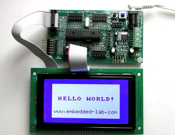
I quickly tested the board with a “Hello World” program, which was written and compiled with mikroC Pro for PIC. I used the built-in GLCD library routines for the test program. An important thing to note here is that the mikroElektronika’s built-in GLCD library works with any KS0108 based 128×64 pixel GLCD that has active low CS1 and CS2 signals. However, the GLCD module that comes with the kit has CS1 and CS2 pins as active high signals. A simple solution to incorporate this difference in the mikroC code is to swap the CS1 and CS2 pins in the program, like this.
sbit GLCD_CS1 at RB5_bit;   // CS1 pin is actually connected to RB4
sbit GLCD_CS2 at RB4_bit;   // and CS2 to RB5
The GLCD library will work just fine after that.

Testing with a "Hello World" program
I also tested the kit by interfacing the DHT11 sensor to the RA0 pin of the PIC16F886 microcontroller, and successfully displayed the relative humidity and temperature values on the GLCD. Read my tutorial on DHT11 to learn more about this sensor.
Download the source and HEX codes for the test program
Download the source and HEX codes for the DHT11 sensor

Temperature and relative humidity measurements using DHT11 sensor
To sum up, this GLCD development kit is pretty handy and is ready to rock right out of the box. Check the following link for pricing and other details of this kit.
ICA05 – GRAPHIC LCD DEVELOPMENT KIT
|
|