XMega I/O Ports
|
|
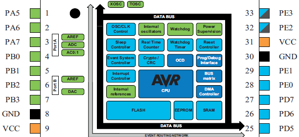
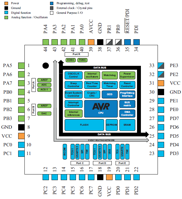
Any microcontroller must have I/O pins for taking inputs and providing outputs. The ATXMega32A4U just like any other micro has 34 programmable I/O pins divided unevenly amongst six IO ports. Most I/O ports are 8 bit wide. XMega I/Os have digital, analog and special purpose functions. Some I/O pins have more than one use. A quick view of the XMega I/O pins reveals the purpose of these pins.
I have always admired Atmel’s documentations, particularly datasheet and reference manuals. They are highly user friendly and when it comes to XMega’s documentations, there is one word I can say “Awesome”. The reference manuals and documentations of XMega devices come in colours, legends and bookmarks and so navigating these docs is pretty easy provided that one knows how to use PDF reader like the Adobe Reader efficiently.
XMega devices are not same as Mega/Tiny AVRs. People who have been using Mega/Tiny AVR will find similarities but not monotony. In Mega/Tiny AVRs there are basically three registers to make an I/O pin/port work and these are DDRx, PINx and PORTx registers. In XMega devices this concept is expanded, allowing more options in designs and coding. People who had played with ARM micros will also find some interesting similarities. Trust me I played with STM32 and AVR micros and I found some striking similarities. These similarities are as such that I can literally anticipate what I’ll find next when I proceed. One such similarity is the alternate function of an I/O pin. This basically allows general purpose I/O pins to do stuffs other than the basic use as a general purpose I/O. Pin remapping is another feature that is common in both XMega and ARM micros. Unlike traditional micros which have dedicated pins for certain internal hardware modules like USART, I2C, SPI, etc. both XMegas and ARMs have an option to relocate dedicated hardware pins from one pin/port position to another. Thus hardware designing become more flexible and easy. It is just why we feel comfortable making stuffs with embedded systems rather than using complex discrete mixed analog-digital circuits. Just imagine, by mistake you wired USART pins wrongly in your design but those I/O port pins’ can be alternatively used as USART pins. This is where you get saved by pin remapping rather than remaking the entire hardware stuff or even making cuts and rewires in the PCB. In a sense pin remapping is a hardware level coding rather than software level coding though this remapping is itself done with a few lines of code.
Before we proceed, I would like to remind readers that in my previous post I stated that Atmel’s software library support allow AVR studio users to code more easily as their header file replaces constants with meaningful names and purposes. As of now MikroC for AVR doesn’t enjoy the fruits offered by Atmel. I realized that I should adopt this feature in MikroC to save both time and efforts, and so I made my own header files containing these constants. Once we enter the code arena we’ll understand how these files come to work. At the time of writing I have just made two such headers – one for the clock system which I previously explained and the other for I/O ports as this will be needed here. I’m expanding the collection of such header files on hardware basis and hopefully I’ll share them in the upcoming posts.
I/O Pin Configurations
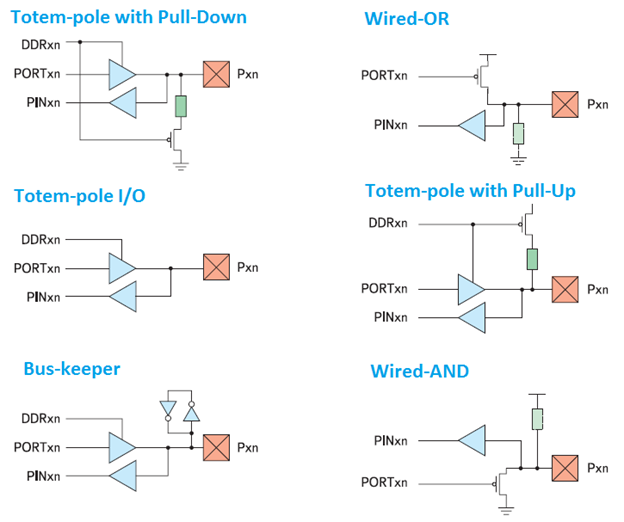
I/O pins in XMega devices have more than the usual general purpose input/output functionality. Shown below are the six possibilities. Wired-AND, Wired-OR and Bus-keeper configurations have limited uses while Totem-pole I/Os are mostly used.
Any XMega reference manual/datasheet briefly describes I/O port configurations but those descriptions are not enough to completely get ideas on how they behave in real world applications. Some people even get confused with the nomenclature of the configurations.
- Totem-pole I/O.
In general a totem-pole I/O is a push-pull type I/O. There is no limit for current source or sink with this configuration except the concerned I/O pin’s maximum current-handling capacity of 20mA. For better understanding on it refer to: http://en.wikipedia.org/wiki/Totem_pole_output. - Totem-pole I/O with Pull Up or Pull Down.
These are same as Totem-pole I/Os but with internal pull resistors for input side only. These configurations are handy for taking inputs from switches and other incoming signal sources. - Bus-Keeper.
In this configuration an input pin latches its last known logic state-high/low even after it went floating. For more info refer to: http://en.wikipedia.org/wiki/Bus-holder. - Wired-AND and Wired-OR.
These two configurations form wired-logic gates which have a number of purposes. According to Atmel’s documentations these configurations are useful when directly connecting two physical I/O pins together. Suppose a GPIO pin is at high logic level and the other is at low logic level then there’ll be a high short circuit current through them. To avoid this situation internal pull resistors are used instead of FET stages to reduce this current. These configurations also behave like real AND and OR gates with respect to their pins. For instance in the Wired-OR configuration, the I/O pin will be at logic high either if it is driven externally high or if its OUT register is set or if in both ways it is set high. Similarly Wired-AND configuration behaves like an AND gate. For more info check this out: http://en.wikipedia.org/wiki/Wired_logic_connection.
Registers
I/O ports are named as PORTA, PORTB, etc. while individual port pins are named as PA6, PB4, etc. There are similarities with both older AVRs and ARMs in terms of naming ports and individual I/O pins.
- DIR registers are responsible for setting data direction of a port or its individual pins. They are just like the DDR registers of Mega/Tiny AVRs. Setting DIR register bits makes corresponding port pins outputs while clearing them makes port pins inputs. There are three more registers that can directly set, clear or toggle DIR register contents. These are DIRSET, DIRCLR and DIRTGL.
- OUT registers are responsible for driving port pins high or low. Again these registers have set, clear and toggle registers associated with them as OUTSET, OUTCLR and OUTTGL to make things easier and faster.
- IN registers can read the logic state of an I/O port pins no matter if the pins are set as outputs or inputs unless input buffers are disabled by coding.
- PINnCTRL registers are registers that are dedicated for individual I/O pins. These registers control the properties of each pins individually. These properties select pull resistors, pin I/O type, slew rate and pin inversion. Please refer to page 151 – 153 of the XMega AU reference manual for details. Usually they are used in a code like this after setting DIR registers:
PORTD_PIN1CTRL = (PORT_OPC_BUSKEEPER_gc | PORT_ISC_BOTHEDGES_gc);
PORTC_PIN4CTRL = (PORT_OPC_TOTEM_gc | PORT_ISC_BOTHEDGES_gc);
- MPCMASK register is used to configure multiple pins with same properties. This ensures lesser code and swift operation. As its name suggests it a mask register and so only the bits set in this register will get configured similarly. To use it first set this register mask as per need and then configure any I/O pin within the mask to get others configured too. Any unmasked pin can also be used and it will remain unaffected but I strongly suggest to use only the masked ones to avoid unnecessary confusion. For instance:
PORTCFG_MPCMASK = 0xFF;
PORTA_PIN6CTRL = (PORT_OPC_TOTEM_gc | PORT_ISC_BOTHEDGES_gc);
- CLKEVOUT register is for outputs related to clock, internal RTC and event system. I guess we already met it in my previous post on XMega. This register just sets which port pin to use to get output from those hardware.
- VPCTRLx and realted-register pairs control virtual port mapping. The I/O instruction set in AVR MCUs can only operate within the AVR I/O space. Using these instructions instead of their data space equivalents is both efficient in terms of code execution time and program memory. All XMega I/O port registers have addresses outside the I/O space. Thus we can use virtual ports. Usually there are four such virtual ports and just like I/O ports they too have DIR, IN and OUT registers.
- There are other register related to I/O ports. These include interrupt-related register, event system, EBI output, etc. I’ll explain them in my later posts when I deal with the related hardware.
Code Examples
As I stated earlier, I made up header files for the required hardware – clock and I/O. In all of the code examples I used them because they make coding easier to understand rather than a bunch of meaningless hexadecimal numbers for each register to be configured and also save precious time configuring them every time when required. The codes themselves are thus self-explanatory. Please be sure to add the files io.h and clock.h with Project Manager when making new codes if you are using my header files or otherwise MikroC compiler will throw tons of errors. Of course we can use raw level coding too without using those header files. It is up to the coder. I made my header files and so can you make your too. In all examples, the CPU is running at 8MHz.
There are six examples and these are:
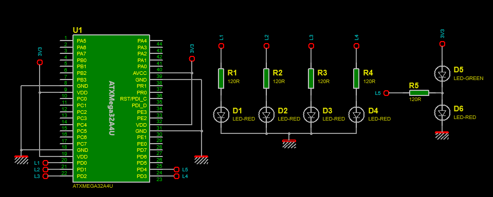
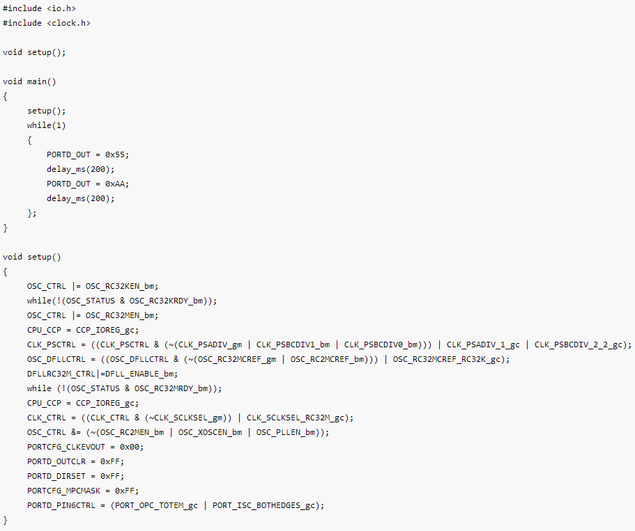
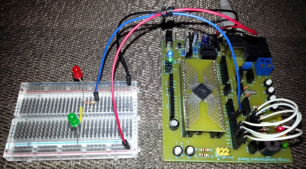
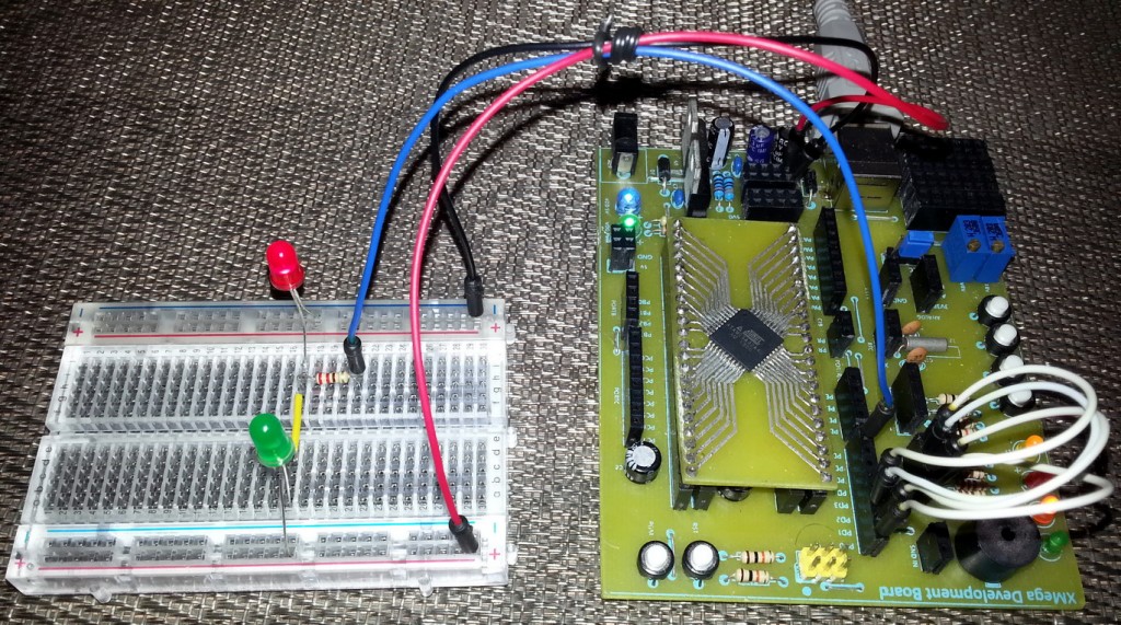
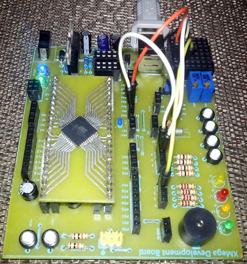
- XMega Basic IO – Totem-pole Output
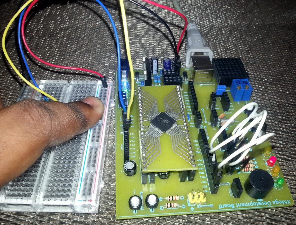
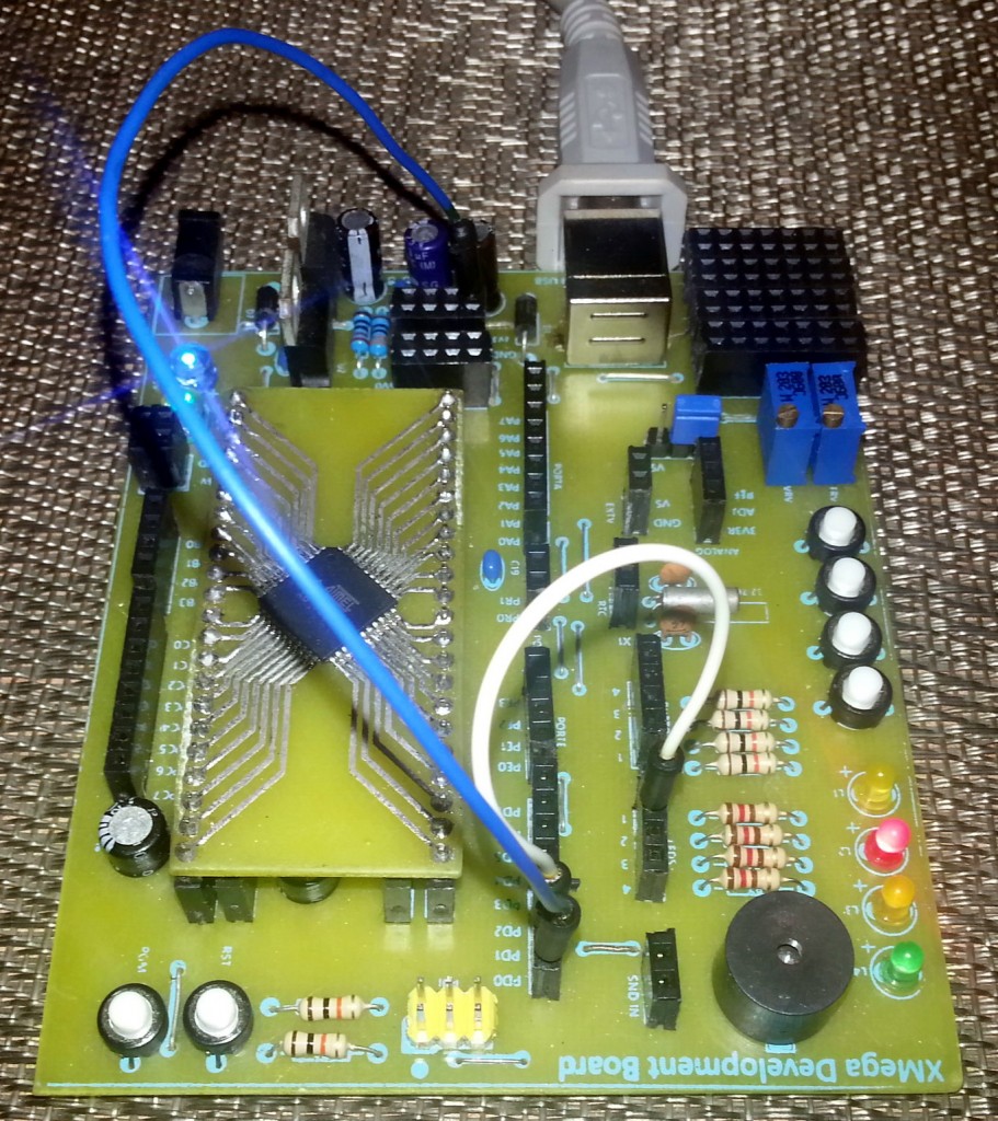
In this example we just blink some LEDs and test the totem-pole output capability.
 Code:
Code:
Video link: https://www.youtube.com/watch?v=r44_UjLxLmo.
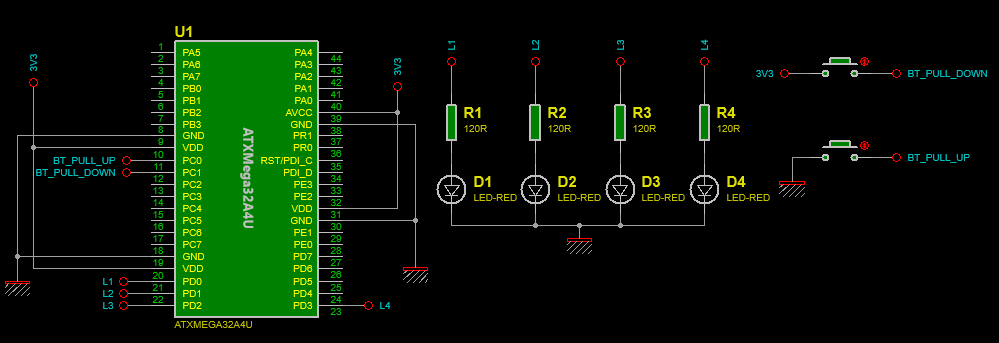
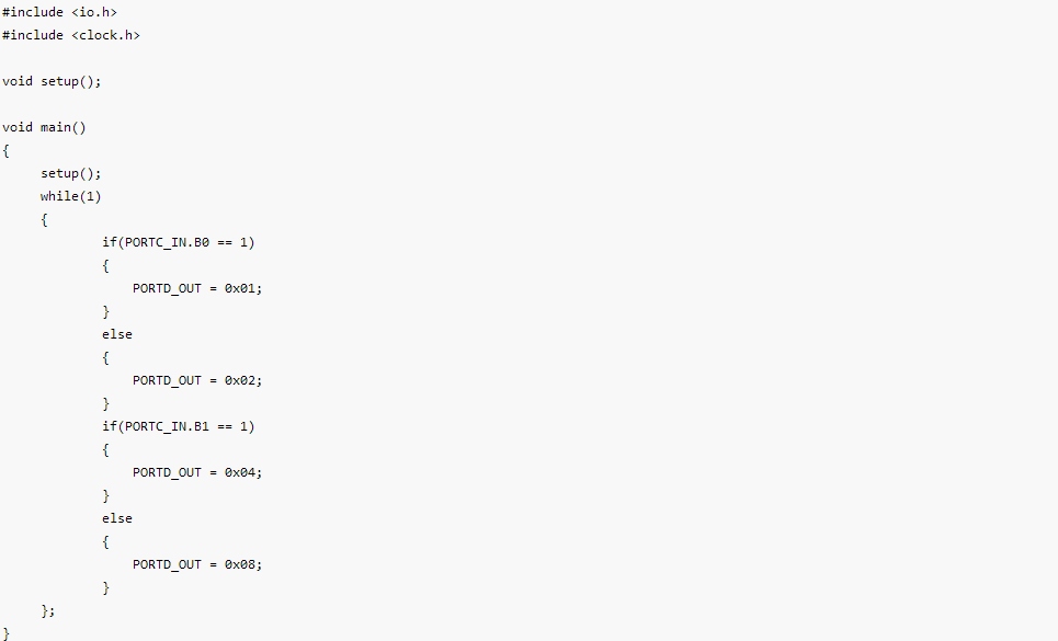
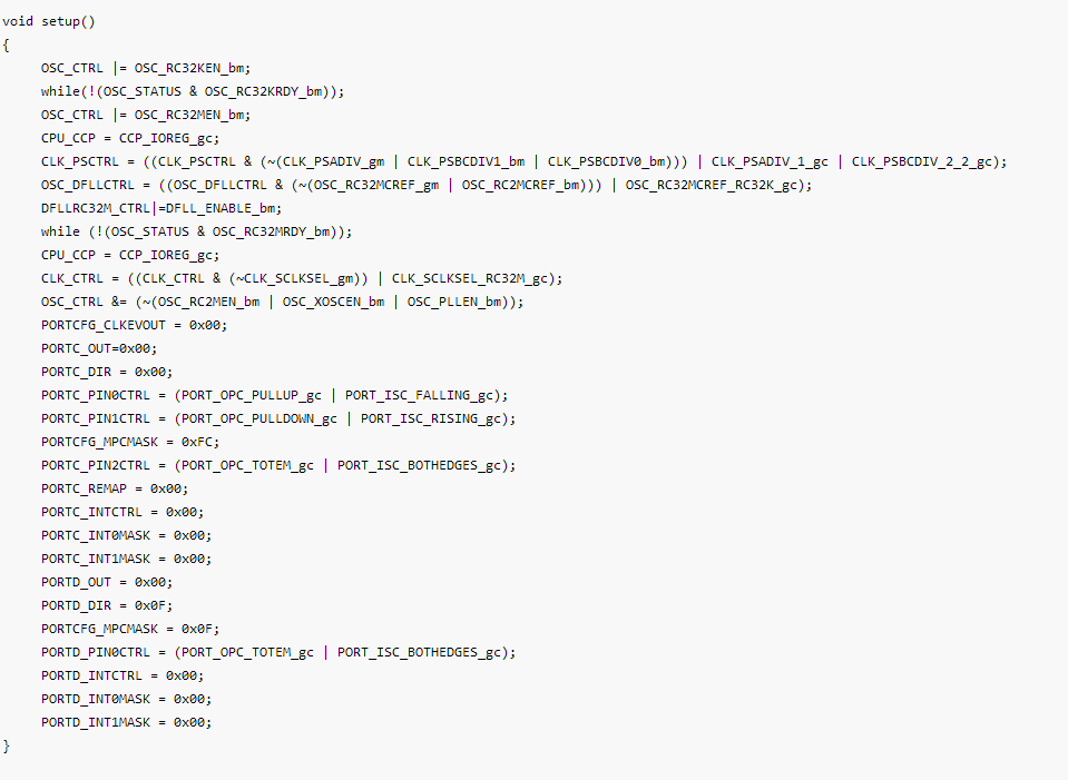
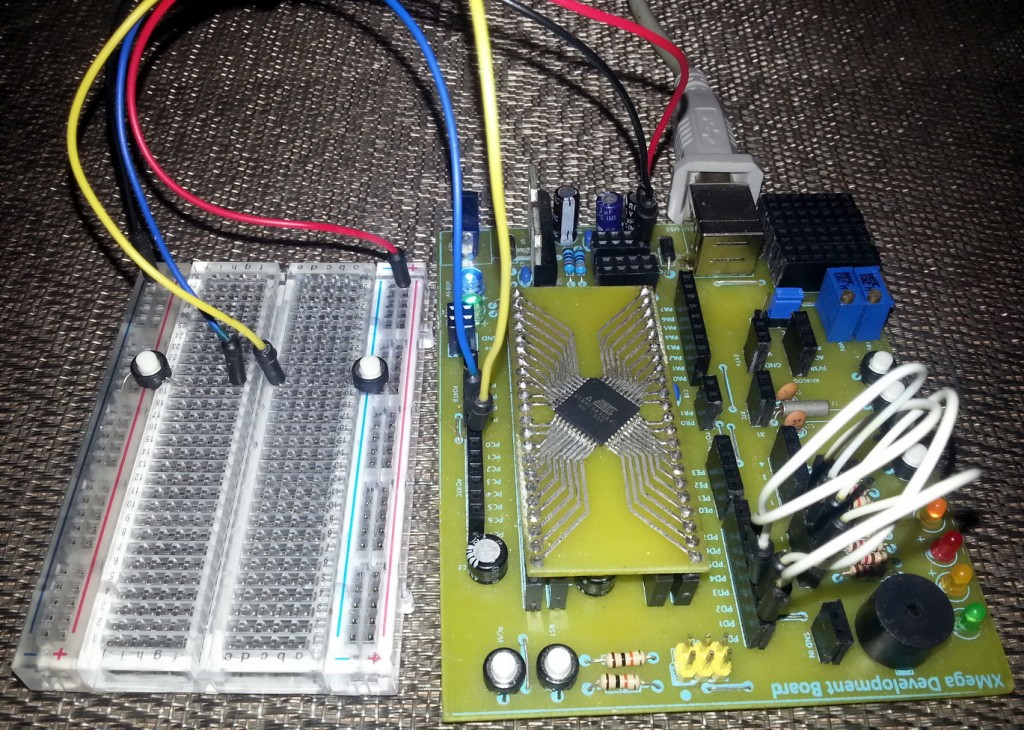
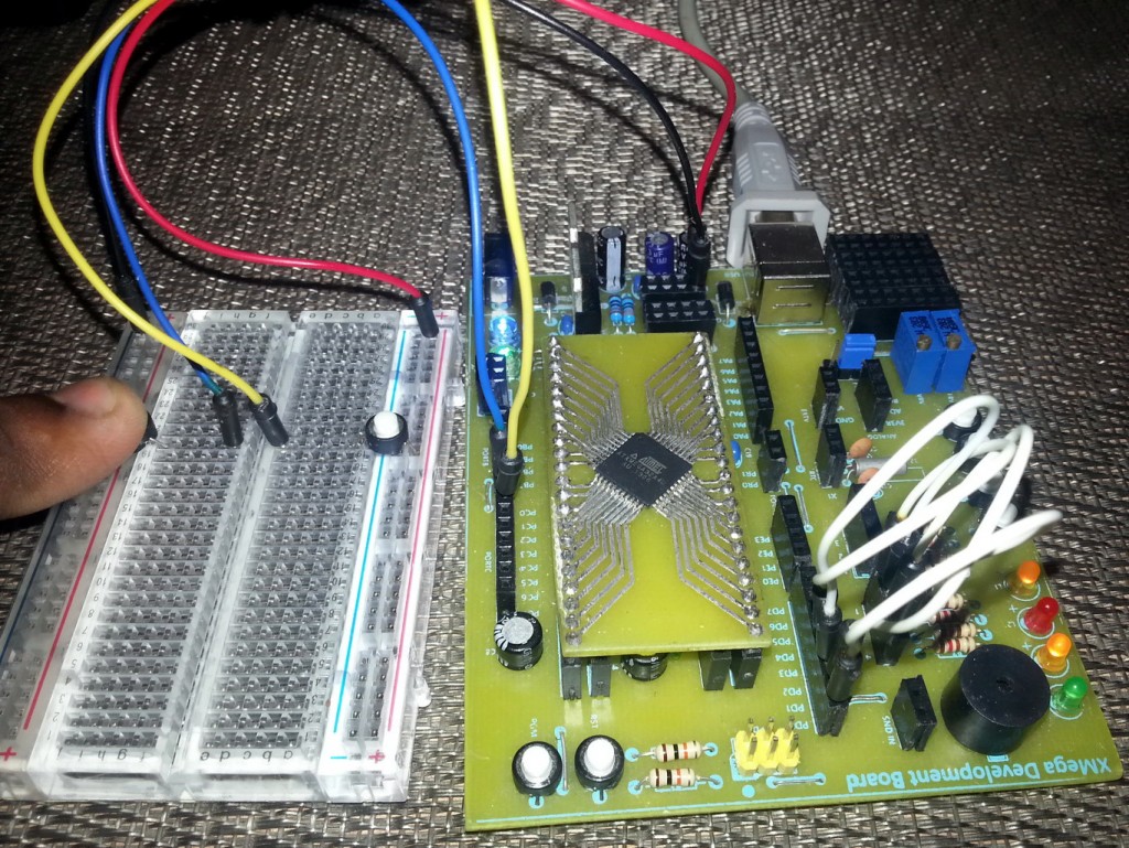
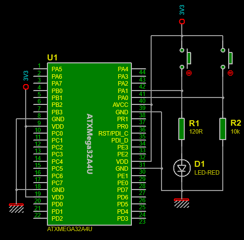
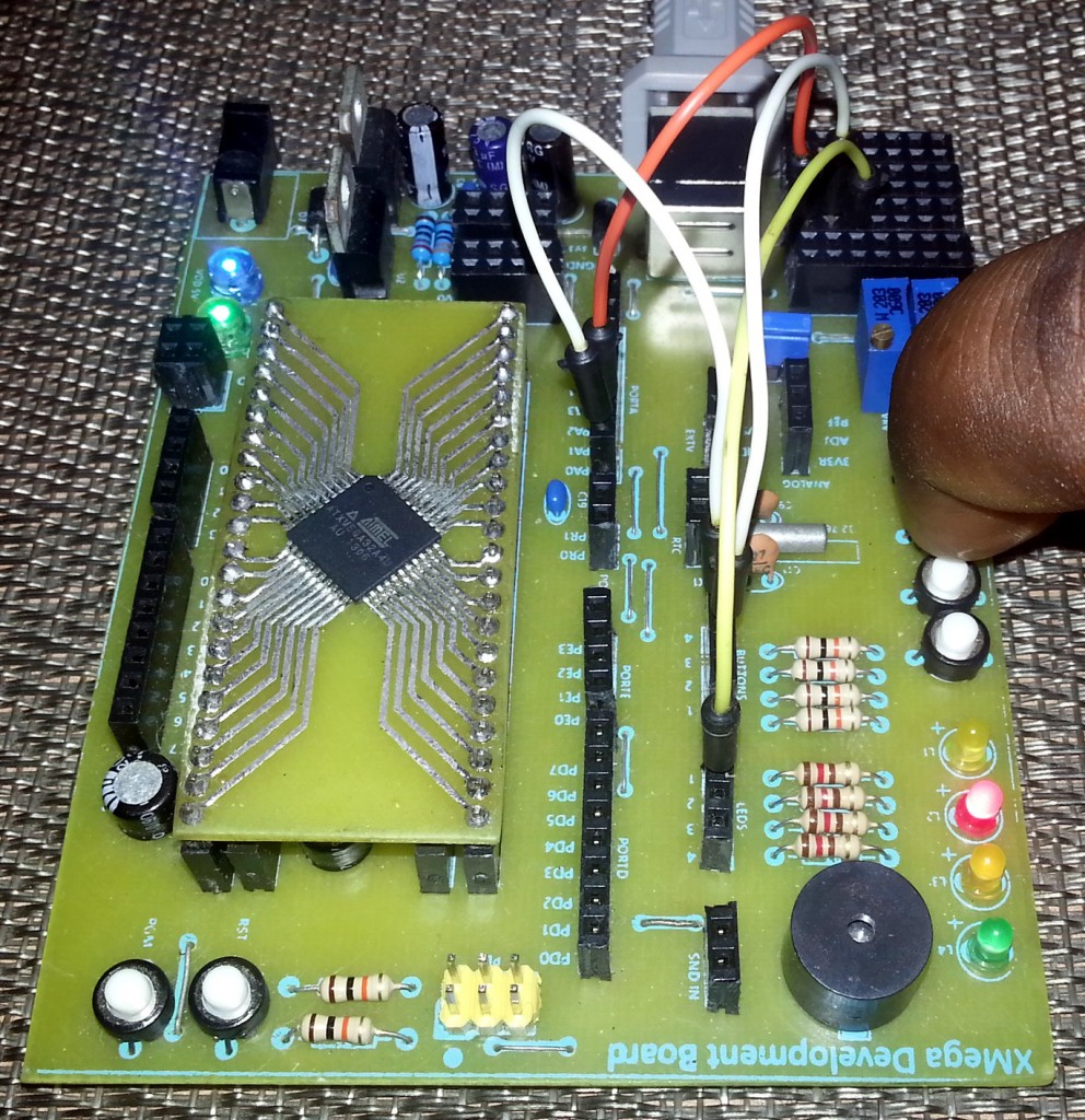
- XMega Basic IO – Inputs with Pull Resistors
In this example, we’ll see the pull-up and pull-down resistors at work when I/O pins are used as inputs.
 Video link: https://www.youtube.com/watch?v=M6M4sxEXu70.
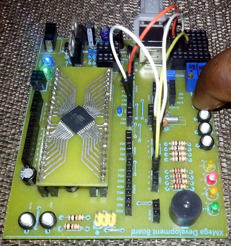
- XMega Advanced IO – Bus-keeper
In this example we’ll see how the bus-keeper configuration works. Please note the latching action of the I/O pin after setting or clearing it and then leaving it to float.
 Code:
Code: 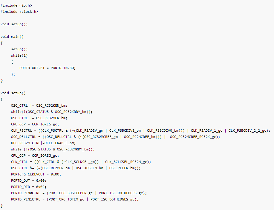
Video Link: https://www.youtube.com/watch?v=ed-EHcd5KAo.
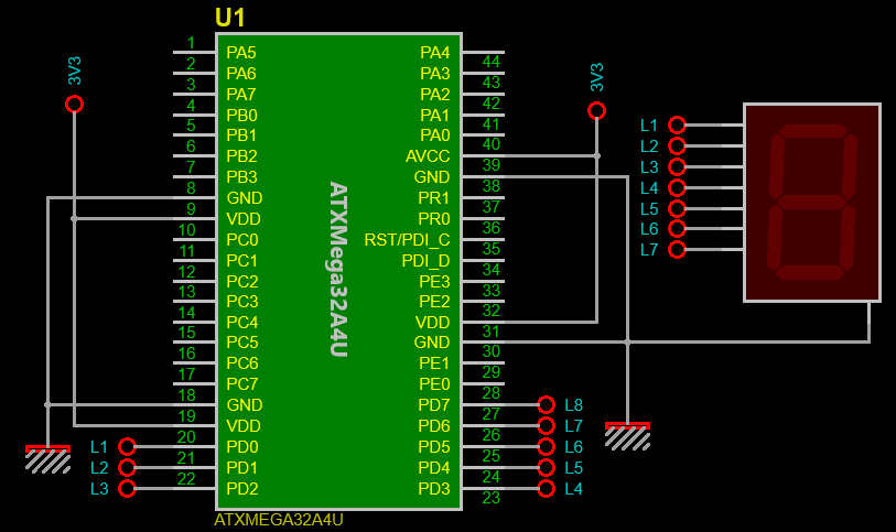
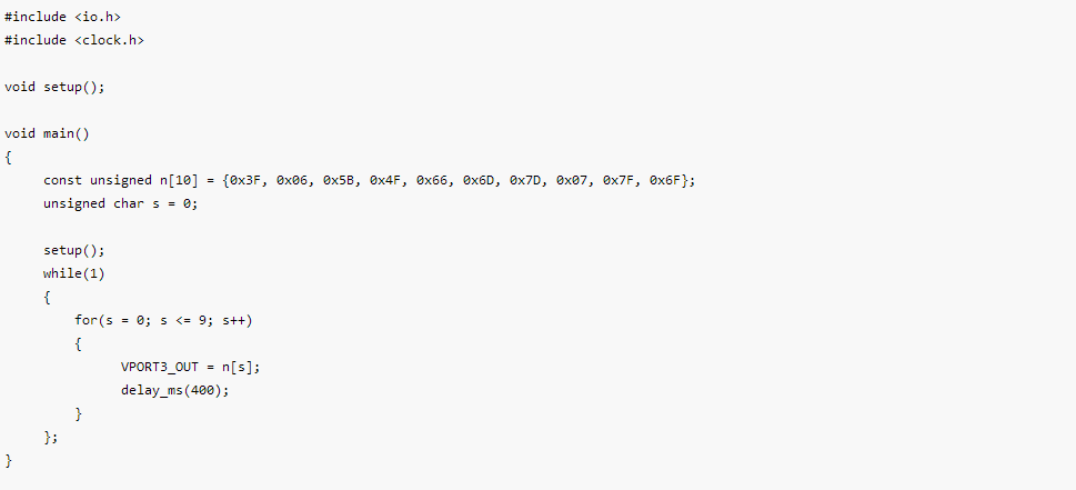
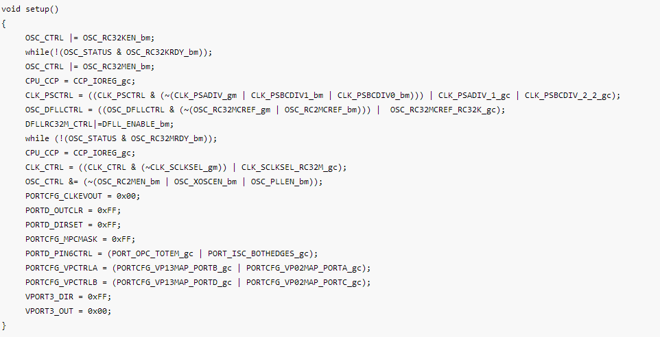
- XMega Advanced IO – Virtual Port
As said before Virtual Ports are used for memory specific instructions and are both fast and code efficient in terms of usage. In this example I mapped PORTD with Virtual Port 3 and made a simple seven segment display counter. Thus writing to Virtual Port 3 is same as writing to PORTD.
Code:
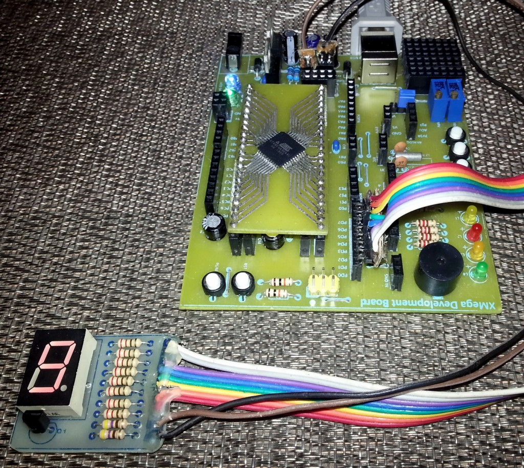
Video Link: https://www.youtube.com/watch?v=cEjAGlrYgCc.
- XMega Advanced IO – Wired-OR
In this example we investigate Wired-OR configuration.

Video Link: https://www.youtube.com/watch?v=T74fPEISz9U.
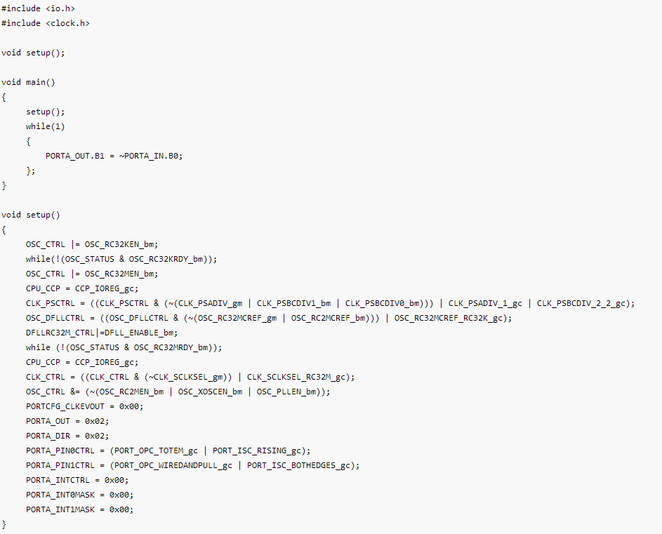
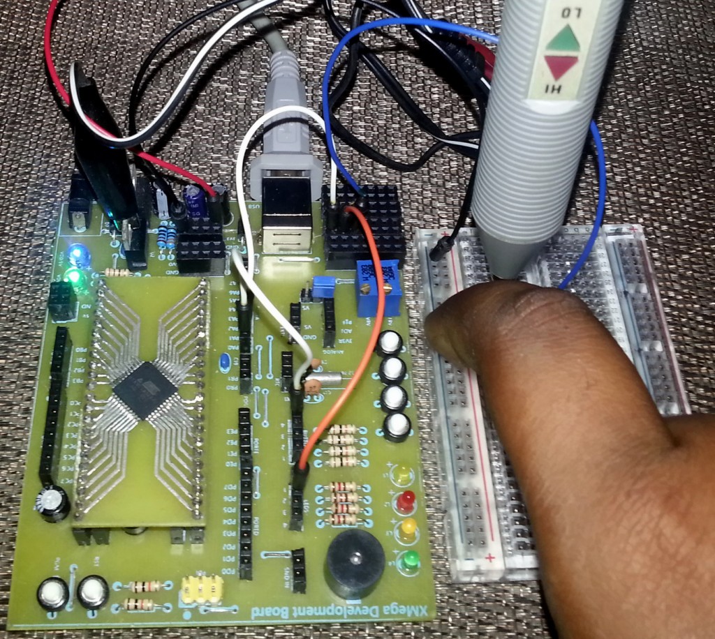
- XMega Advanced IO – Wired-AND
In this example we investigate Wired-AND configuration. Please note I tested this configuration with a logic probe instead of a LED as the pull resistor’s resistance is too directly drive a LED.
 Code:
Code:
 Video Link: https://www.youtube.com/watch?v=QbVIEtwzqqo.
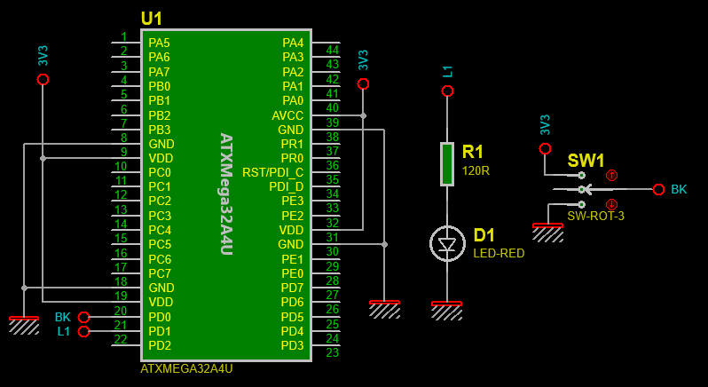
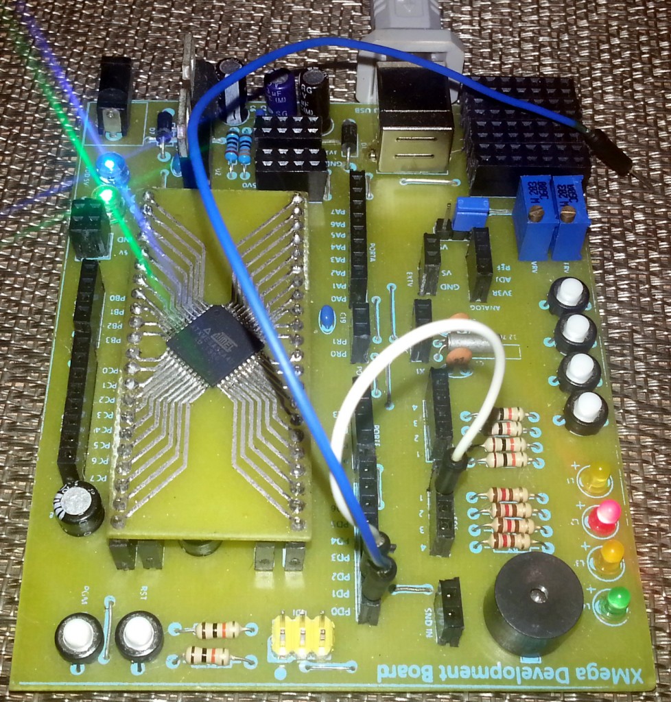
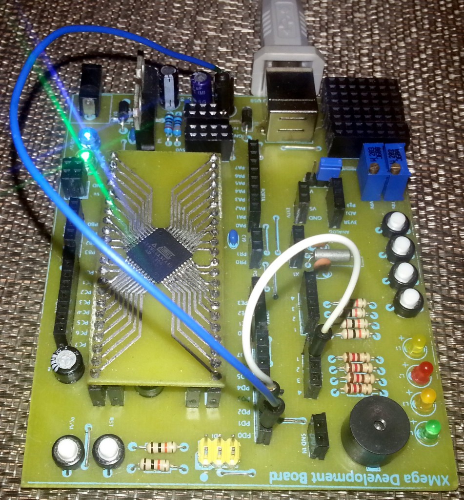
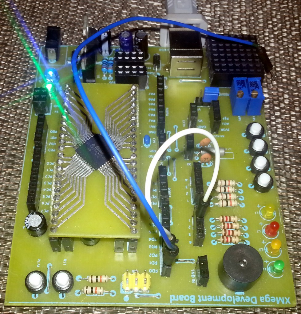
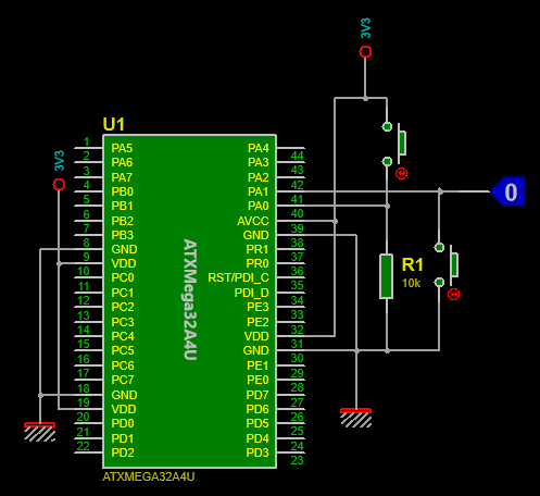
Before any confusion start to develop amongst readers regarding the schematic designing tool I used, I would like to inform them that all schematics in this post were made with Proteus VSM. However Proteus VSM doesn’t support XMega chips and so everything that was discussed here were done with real hardware instead of software simulations. Trust me hardware level debugging is more useful than software/simulation-based debugging.
I hope this post helped people to clear a number of confusions and paved ways for new concepts regarding XMega I/O port. Trust me I too had a lot of questions before exploring the XMega I/O ports because info on XMega devices are too scattered and incomplete.
In my final words just like any other post, I’ll recommend readers to go through the XMega AU reference manual at least once. This will seriously help. Keep practicing what you have learnt so far and explore new ideas.
Happy coding.
Files: XMega IO Ports.
Author:
Shawon M. Shahryiar
https://www.facebook.com/groups/microarena/
https://www.facebook.com/MicroArena
|
|
Clear and helpfull explanation.
best regards
Robert
Thanks for this! I agree that the Xmega docs are somewhat disjointed – very confusing sometimes.
For example, I discovered yesterday that
PORTA.DIRSET = 0xf0;
PORTA_DIRSET = 0x0f;
are interghangeable – disassembles the same, but nowhere can I find mention of this….
Anyway, I’ll read Your stuff avidly!
-Cheers
-Andy