Temperature and relative humidity display with adaptive brightness control
|
|
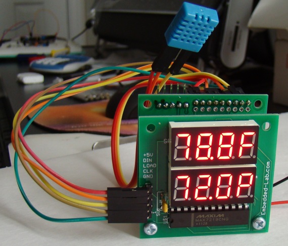
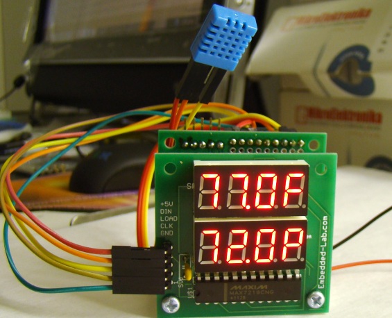
The objective of this project is to illustrate a technique of implementing adaptive brightness control to seven segment LED displays. It consists of a closed loop system that continuously assesses ambient light condition using an inexpensive light-dependent resistor (LDR) and uses that information to adjust the brightness of the display. For the proof of concept, the technique is applied to construct a digital temperature and relative humidity meter that adapts the brightness of the seven segment LED displays to the surrounding lighting conditions. There are 8 seven segment LED displays used in this project and they are all driven by one MAX7219 chip. The ambient temperature and relative humidity are measured using the DHT11 sensor. The microcontroller used in this project is PIC12F683, which is a low-pin-count (8) device from 8-bit PIC microcontroller family. Auto-adjusting the brightness of the seven-segment LED display with surrounding illumination enhances the readability in all ambient lighting conditions.
Theory and circuit setup
Many smartphones, HDTVs, PDAs, tablets, and computer screens now come with an automatic brightness control that aims to conserve power as well as to make the display easier to see in a broad range of illumination conditions. This feature basically dims the display screen in a dark environment and brightens it when the ambient light level is higher. The brighter screen helps to counteract the effects of glare from ambient light and also takes into account for the decreased sensitivity of human eyes to brightness as the ambient light level increases.
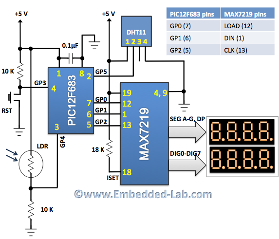
An automatic brightness adjustment is basically a closed loop system that has the capability to assess ambient light and adjust the brightness of the display accordingly. In our project, a general purpose LDR and a fixed value resistor (10K) are connected in series between the power supply and ground pins to create a voltage dividing network, as shown in the circuit diagram below. The resistance of a typical LDR is less than 1 K? under bright lighting condition. Its resistance could go up to several hundred K? under extremely dark condition. Therefore, the voltage across the 10K resistor increases proportionally with the surrounding illumination. For the given setup, the voltage across the 10K resistor can vary from 0.1V (under dark condition) to over 4.0V (under very bright illumination). The PIC12F683 microcontroller reads this analog voltage through its AN3 (GP4) ADC channel and then sends out appropriate signals to the MAX7219 display driver to adjust the brightness of the seven segment LED displays.
The MAX7219 chip provides a serial interface to drive 7-segment LED displays (common-cathode type) up to 8 digits and requires only 3 I/O pins from microcontroller. Included on the chip are a BCD decoder, multiplex scan circuitry, segment and digit drivers, and an 8×8 static RAM to store the digit values. The segment current for all LEDs is set through only one external resistor connected between the ISET pin and power supply. However, the device also provides a digital control of the display brightness (16 steps from minimum to maximum) through an internal pulse-width modulator. To learn more about the MAX7219 device, read my previous article Serial 4-digit seven-segment LED display. In this project, the GP0, GP1, and GP2 I/O pins of PIC12F683 are used to drive LOAD, DIN, and CLK signal lines of the MAX7219.
In order to measure the temperature and relative humidity, the DHT11 sensor is used. It can measure temperature from 0-50 °C with an accuracy of ±2°C and relative humidity ranging from 20-95% with an accuracy of ±5%. The sensor provides fully calibrated digital outputs for the two measurements. It has got its own proprietary 1-wire protocol, and therefore, the communication between the sensor and a microcontroller is not possible through a direct interface with any of its peripherals. The protocol must be implemented in the firmware of the MCU with precise timing calculations required by the sensor. I have described more about this sensor and its communication protocol in Measurement of temperature and relative humidity using DHT11 sensor and PIC microcontroller. The PIC12F683 uses the GP5 I/O pin to communicate with the DHT11.
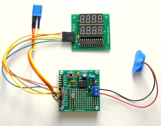
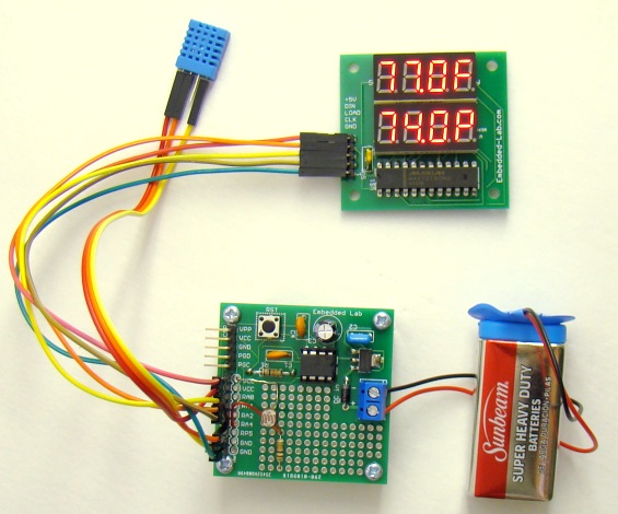
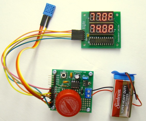
To make prototyping easier, I am using my PIC12F Project board and my Serial 8-digit seven segment LED display in this project.
Software
The firmware for this project is written in C and compiled with mikroC Pro for PIC compiler version 5.30. The subroutines for initializing the MAX7219 and sending display-digit bytes are written in a simple and understandable way so that they can be easily implemented with any other programming language. If you are not familiar with MAX7219’s internal control and display registers, I would recommend to read one of my earlier posts, Serial 4-digit seven-segment LED display. The MAX7219 allows display brightness to be controlled through software by an internal pulse-width modulator (PWM). The PWM output is controlled by the lower nibble (D3-D0) of the intensity register (address 0x0A) and allows 16 brightness levels. The zero nibble value sets the display intensity to minimum, whereas all nibble bits set to 1 selects the maximum intensity level for the display. For auto-brightness control, the ADC output of the LDR sensor is first scaled down to 0-10 (11 brightness levels) by simply dividing the 10-bit ADC count by 100. Then a look-up table is used to map the scaled brightness levels to appropriate nibble values for the intensity control register of the MAX7219. The temperature is displayed in Fahrenheit (F) scale and the relative humidity in percentage (P).
// Define Software-SPI connections for MAX7219 #define CS_Pin GP0_bit #define MOSI_Pin GP1_bit #define CLK_Pin GP2_bit // Define Data pin for DHT11 #define Data GP5_bit #define DataDir TRISIO5_bit unsigned short TOUT = 0, CheckSum, i; unsigned short T_Byte1, T_Byte2, RH_Byte1, RH_Byte2; unsigned short check, brightness=0x0b; unsigned int counter = 0, TempF, RH, ADC_OP; unsigned short Brightness_Table[11] = {0, 1, 2, 4, 5, 7, 9, 11, 12, 14, 15}; void SPI_Write_Byte(unsigned short num){ unsigned short t, Mask, Flag; CLK_Pin = 0; Mask = 128; for (t=0; t<8; t++){ Flag = num & Mask; if(Flag == 0) MOSI_Pin = 0; else MOSI_Pin = 1; CLK_Pin = 1; CLK_Pin = 0; Mask = Mask >> 1; } } void MAX7219_INIT() { // Disable Shutdown mode CS_Pin = 0; // CS pin is pulled LOW SPI_Write_Byte(0x0C); // Select Shutdown register SPI_Write_Byte(0x01); // Set D0 bit to return to normal operation CS_Pin = 1; // CS pin is pulled HIGH // Set BCD decode mode for digits DIG1-DIG3, and DIG5-DIG7 CS_Pin = 0; // CS pin is pulled LOW SPI_Write_Byte(0x09); // Select Decode Mode register SPI_Write_Byte(0b11101110); // Disable BCD mode for digits DIG0-DIG4 CS_Pin = 1; // CS pin is pulled HIGH // Set display brighness CS_Pin = 0; // CS pin is pulled LOW SPI_Write_Byte(0x0A); // Select Intensity register SPI_Write_Byte(brightness); // Set brightness CS_Pin = 1; // CS pin is pulled HIGH // Set display refresh CS_Pin = 0; // CS pin is pulled LOW SPI_Write_Byte(0x0B); // Select Scan-Limit register SPI_Write_Byte(0x07); // Select digits DIG0-DIG3 CS_Pin = 1; // CS pin is pulled HIGH // Enable Display-Test CS_Pin = 0; // CS pin is pulled LOW SPI_Write_Byte(0x0F); // Select Display-Test register SPI_Write_Byte(0x01); // Enable Display-Test CS_Pin = 1; // CS pin is pulled HIGH Delay_ms(1000); // Disable Display-Test CS_Pin = 0; // CS pin is pulled LOW SPI_Write_Byte(0x0F); // Select Display-Test register SPI_Write_Byte(0x00); // Disable Display-Test CS_Pin = 1; // CS pin is pulled HIGH } void Display_Value(unsigned int j, unsigned short k){ CS_Pin = 0; // CS pin is pulled LOW SPI_Write_Byte(k); // Send thousands digit SPI_Write_Byte((j/100)%10); CS_Pin = 1; // CS pin is pulled HIGH CS_Pin = 0; // CS pin is pulled LOW SPI_Write_Byte(k-1); // Send hundreds digit SPI_Write_Byte(((j/10)%10) | 0x80); CS_Pin = 1; // CS pin is pulled HIGH CS_Pin = 0; // CS pin is pulled LOW SPI_Write_Byte(k-2); // Send tens digit SPI_Write_Byte(j%10); CS_Pin = 1; // CS pin is pulled HIGH CS_Pin = 0; // CS pin is pulled LOW SPI_Write_Byte(k-3); // Send ones digit if(k == 4 ) SPI_Write_Byte(0x47); // Display 'F' if(k == 8 ) SPI_Write_Byte(0x67); // Display P CS_Pin = 1; // CS pin is pulled HIGH } void StartSignal(){ DataDir = 0; // Data port is output Data = 0; Delay_ms(25); Data = 1; Delay_us(30); DataDir = 1; // Data port is input } unsigned short CheckResponse(){ TOUT = 0; TMR2 = 0; T2CON.TMR2ON = 1; // start timer while(!Data && !TOUT); if (TOUT) return 0; else { TMR2 = 0; while(Data && !TOUT); if (TOUT) return 0; else { T2CON.TMR2ON = 0; return 1; } } } unsigned short ReadByte(){ unsigned short num = 0, t; DataDir = 1; for (i=0; i<8; i++){ while(!Data); TMR2 = 0; T2CON.TMR2ON = 1; while(Data); T2CON.TMR2ON = 0; if(TMR2 > 40) num |= 1<<(7-i); // If time > 40us, Data is 1 } return num; } void interrupt(){ if(PIR1.TMR2IF){ TOUT = 1; T2CON.TMR2ON = 0; // stop timer PIR1.TMR2IF = 0; // Clear TMR0 interrupt flag } } void Display_Brightness(){ CS_Pin = 0; // CS pin is pulled LOW SPI_Write_Byte(0x0A); // Select Intensity register SPI_Write_Byte(brightness); // Update brightness CS_Pin = 1; // CS pin is pulled HIGH } void main() { TRISIO=0b00011000; // GP3, GP4 are input CMCON0 = 0x07; ANSEL = 0x08; // AN3 active INTCON.GIE = 1; //Enable global interrupt INTCON.PEIE = 1; //Enable peripheral interrupt // Configure Timer2 module PIE1.TMR2IE = 1; // Enable Timer2 interrupt T2CON = 0; // Prescaler 1:1, and Timer2 is off initially PIR1.TMR2IF =0; // Clear TMR INT Flag bit TMR2 = 0; MAX7219_INIT(); // initialize max7219 do{ ADC_OP = ADC_Read(3); ADC_OP = ADC_OP/100; Brightness = Brightness_Table[ADC_OP]; Display_Brightness(); StartSignal(); check = CheckResponse(); if (!check) { TempF = 0; RH = 0; } else{ RH_Byte1 = ReadByte(); RH_Byte2 = ReadByte(); T_Byte1 = ReadByte(); T_Byte2 = ReadByte(); CheckSum = ReadByte(); // Check for error in Data reception if (CheckSum == ((RH_Byte1 + RH_Byte2 + T_Byte1 + T_Byte2) & 0xFF)) { TempF = 10*T_Byte1; TempF = 9*TempF/5 + 320; RH = 10*RH_Byte1; } else{ TempF = 0; RH = 0; } } Display_Value(TempF, 4); Display_Value(RH, 8); Delay_ms(500); }while(1); } |
The PIC12F683 microcontroller runs at 4.0 MHz internal clock. The MCLR and Power-On Timer are both enabled. The complete configuration bit settings are shown below.
Output
The project was tested under different lighting conditions, varying from very dark to very bright, and all the time display was found readable and eye-soothing. If you want to put something like this in your bedroom, you don’t have to worry about turning it off during nighttime. The display will automatically dim enough so as not to disturb your sleep. While the given look-up table for brightness intensity provides satisfactory adjustment of brightness level at different lighting condition, you can still tweak these numbers to find the best matches for your eyes.
|
|


I want to use this code in MPLABX IDE. Please let me know in function SPI_Write_Byte what is that variable means like t<, &, > since it is not defined in code.
No funciona….tiene aluna corrección……?
Lo simulo con Proteus y no funciona, agradecería ayuda.
Muchas gracias.
I have been trying to get the circuit to run for the past two months without success. The Hex files loaded fine the circuit works and displays the value. There is one hitch though. The temperature does not seem to change and is static. The humidity values also does not come close to the lab hygrometer that we have, Further, I need to change from F to C. Is there something that I am not doing right? I am a beginner with Microprocessors so I am not very conversant in writing the program. Can you please help me out on this? Is there any place I can upload my Hex files for you to check. If you can send in the corrected Hex file, that would be great. Thanks
A good project.
Really like this project with HEX for Celsius.I started by controllers.
I do not know how to write programs.Thank you!
Can not get the hex to run. It lods but wont run in the circuit.
Is there some thing I need to do to the file to get it to work.
would love help thank you.
can you help me by k type thermocouple interface circuit to microcontroller.
i tried with many but opamp output is too noisy and fluctuate about 10 to 20mv
i am making a project on automatic irrigation system using pic microcontroller using humidity sensors. i need help regarding which microcontroller to be used and coding to interface humidity sensors and solenoid valves.
what to do
Pingback: How to implement auto-brightness adjustment to seven segment LED displays | electronics-projects.info