ATXMega Primer
|
|
The XMega series is a powerful addition to the existing arsenal of Atmel’s AVR-core micros. As much as I have personally studied about it so far and felt, the XMega series incorporates many features of conventional 32-bit ARM micros like alternate I/O pin mapping functionalities, sophisticated clock options and data buses, multiple communication platforms that have several uses, variety of capture-PWM options, 12-bit ADCs and DACs, DMA controller, USB hardware, etc. with the good old AVR core. Thus you get one hell of an 8/16 bit MCU that can fulfil your wildest micro desires. In terms of unit cost, resources and user flexibilities this family of micro can beat any present day micro in most of the scenarios. Unlike other manufacturers who design chips as to fit specific applications, there’s no limit for XMega series. It is one controller with unlimited possibilities that can fit into any application. Indeed it is a true Atmel slogan now:
“My microcontroller can beat the hell out of your microcontroller.”
There are several things that are should be known. XMega is still a relatively new breed of micro. There’s literally nothing similar to it in the market no matter which manufacturer you can name. As I said Atmel added literally everything that can be imagined. Initial XMega devices had several hardware flaws and were unstable. They had problems related to power and operational stability. However these shortcomings are no longer there as they were. Atmel dramatically improved this new line of devices and are yet doing a lot of R&D on it. The older successful AVR Mega series micros are not as same as XMegas and so what can be applied to Mega AVR can’t be applied for the XMegas. There are significant differences both in terms of hardware and software but still there are similarities.
At present we have different families of XMega devices. Of these many we are focused toward the AU series only throughout this post and its following ones. I’ll explain later why I’m interested in this series. This is the first post of a series of posts that I’ll be publishing time-to-time. Well I should admit that making tutorial notes is not my favourite hobby but it helps me to keep documentations for future uses, reference, etc. and at the same time help others to get an easy access that I have crossed with lot of difficulties. I must also say that I’m not a good author when it comes to books, notes or other form of documentation and so if anywhere throughout the series should you find something wrong please don’t hesitate to inform me. Through these posts, I’ll try to explain as much as possible but I’ll suggest the readers to go through XMega manuals available at Atmel’s website http://www.atmel.com before starting to play with the chips themselves. These manuals are way too large to explain down to every bits and pieces and so, at least at the time of writing this doc, there are very few resources available in the internet in a scattered fashion. Very few people have worked with XMegas and not everyone shared their collective knowledge. Even at this time there’s no book on this micro family. It should also be noted that due to XMega’s unavailability in DIP versions, complex internal hardware and lack of support in popular simulator software like the Proteus VSM, the XMega series is still not that much popular amongst hobbyist and DIYers. Arduino developers even moved to ARM micros rather than choosing XMega. XMega MCUs are also relatively new and form a different family of micros that are only of their kind. Hardly can I find any other 8/16 bit MCU with so much robustness and agility. All these are just the opposite for the popular PIC or Mega/Tiny AVR micros. For basic questions on XMega vs Mega AVR and baseline info refer to this doc: http://www.atmel.com/Images/doc8169.pdf.
XMega Features
These are what Atmel’s website have to say about XMega family in short.
- High-precision analog peripherals — 12-bit ADCs with gain stage and combined throughput of 4MSPS. Fast 12-bit DACs with high drive strength, as well as other functions that reduce the need for external components.
- Real-time performance — The Event System facilitates inter-peripheral signalling with 100% predictable response time.
- Atmel picoPower® technology — True 1.6V operation, and down to 100nA RTC operation with full SRAM retention for fastest possible wake-up time.
- High integration — AVR XMEGA devices integrate Advanced Encryption Standard (AES) and Data Encryption Standard (DES) crypto modules, up to 32 pulse-width modulation (PWM) outputs, 8 UARTs, 4 TWI (I2C) and 4 serial peripheral interface (SPI) channels, DMA, a cyclic redundancy check (CRC) generator module and more.
- Atmel QTouch® Sensing — Capacitive touch-based buttons, track pointers and interface inputs can be realized with XMegas.
- USB connectivity — Delivers full-speed operation without the need for external crystals, 31 endpoints, and a special multi-packet function that maximizes data transfer rates while minimizing CPU load.
- XMEGA Custom Logic (XCL) — The XMega E devices feature an innovative XMega Custom Logic module (XCL) consisting of two independent 8-bit timers/counters and two lookup tables used for defining glue logic. It is designed to reduce bill of material (BOM) and PCB size as the XCL can replace external circuitry such as delay elements, RS-latches, D-latches, D-flip-flops chip-select logic, AND, NAND, OR, NOR, XOR, XNOR, NOT, MUX AND/OR/XOR logic gates. In addition, it can, together with the USART, enable customized communication protocols.
Hardware-Software Tools
First things first. What we’ll need to get started.
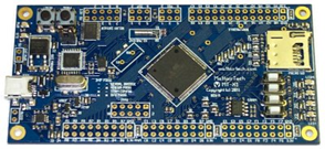
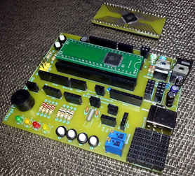
- An XMega chip embedded in a DIP converter/Plug-in-Module (PIM) or an XMega development board. Any XMega chip will do but I prefer the A4U series, specifically ATXMega32A4U or ATXMega128A4U as they have USB support for DFU bootloader and most of the common internal hardware found XMega micros. These chips are like flagships of the XMega series while at the same time cheap. I’ll be using the XMega32A4U along with my custom made development board.

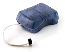
- A programmer that supports PDI/JTAG interface. I say that you get an official Atmel programmer. JTAG ICE or AVR ISP MKII will suffice. Refer to device manuals and check which interfaces can be used to program your XMega. For instance the chip that I’ll be using – XMega32A4U supports only PDI interface while other XMegas support both PDI and JTAG. You’ll not need a programmer if your XMega chip was shipped with the XMega bootloader or if you don’t need to alter fuse settings. Be careful about buying these official Atmel programmers because there are many fake copies of them that don’t work as they should. Buy them from a genuine Atmel distributor.
- Software that we’ll need include MikroC PRO for AVR, Atmel AVR Studio (for programmer only), http://www.atmel.com/microsite/atmel_studio6/ and Atmel Flip (for bootloader application), http://www.atmel.com/tools/flip.aspx. Of course we can use AVR Studio, Codevision AVR, BASCOM, etc for coding XMegas but I’m not going for any one of them. Name it a personal choice or something else. I’ll stick to MikroC as I’m using the same tool for ARM too. Changing a compiler IDE and my entire establishment for just a family of micro sounds like crazy ride to me.
- Rest of the stuffs that will be needed include basic lab tools like multimeters, power supplies, an oscilloscope, a signal generator, connecting wires, bread boards, etc. A well regulated DC power supply is a must. The other tools may be ignored but I recommend having them during work.
- Additionally download the XMega AU manual from here: http://www.atmel.com/images/atmel-8331-8-and-16-bit-avr-microcontroller-XMega-au_manual.pdf.
The Bootloader
The ability of XMega32A4U to get programmed via the XMega USB DFU bootloader makes it very easy to get hands on it without worrying about an external programmer hardware. Most chips are shipped with this bootloader. However not all are shipped this way. In this section, I’ll explain how to get the bootloader into a fresh bootloader-less XMega chip and what steps will required to be done. Please download the XMega32A4U bootloader file supplied in this post.
Unlike traditional AVRs like the ATMega32A which typically use SPI-based ISP for programming, XMegas generally use PDI interface.
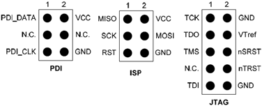
As can be seen there’s no similarity between PDI and SPI-based ISP. PDI interface is somewhat like I2C because it use two wires for data communication – PDI-data and PDI-clock. At this point I’ll not go further about PDI interface as it is beyond the scope of this post. For further info on PDI refer to: http://support.atmel.com/bin/customer.exe?=&action=viewKbEntry&id=683.
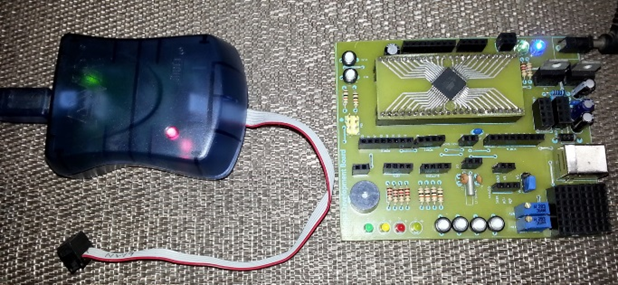
Before you go ahead keep in mind that XMegas don’t operate at 5V. They need 3.3V power supply. Thus unless you are using a development platform/board I would recommend that you wire up your basic setup in a decent manner and use a regulated 3.3V power supply. If you are using USB port to power your XMega be sure to use a 3.3V LDO regulator. I also recommend applying 100nF – 10uF tantalum capacitors adjacent to the power supply pins of the XMega chip. Keep those caps as close as possible to the VDD-GND pins of the micro. This will ensure stable and noise free power source for the chip. It’s also worth noting that the official Atmel programmers like the AVR ISP MKII which I’ll be using, don’t power the target micro unlike other programmers like the Microchip PICKIT2 or PICKIT3 or even the clone USBASPs. This is where, according to me at least, official Atmel programmers suck. Thus before using an official programmer make sure that your target chip is powered. Alternatively you can add a switchable power supply (3.3V-5V) to your official Atmel programmer. Refer to this video on this by EEVBlog’s Dave: https://www.youtube.com/watch?v=ICQXqVy3Hpc. See how he modified his MKII ISP.
Below is the schematic of a minimal level XMega board. You can use it if you wish.
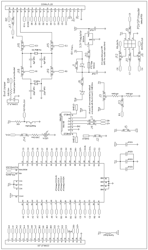
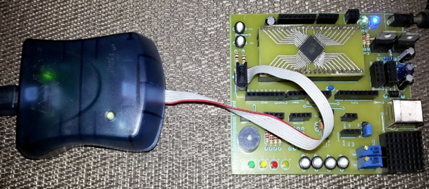
Check how the PDI interface is connected (pin no. 34 and 35). You should also connect it this way and hook up your programmer according to pin names. Hooking the programmer PDI port the other way around or wrongly won’t cause any serious issue but you’ll get errors and your programmer won’t find your target MCU. Be very careful about this.
Provided that everything has been done properly and your setups are ready to go, connect your programmer with your PC and open AVR Studio IDE. Power your XMega and connect it with your programmer’s PDI interface properly. Refer to pages 30 – 35 of the XMega AU manual for info on fuse and lock bit settings before changing them. In most cases you won’t have to mess with fuse and lock bits. In the AVR Studio IDE go to Tools and then select Device Programming. This will check for tools available for programming and will also provide an interface to use the connected programmer.
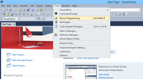
A new window will pop up.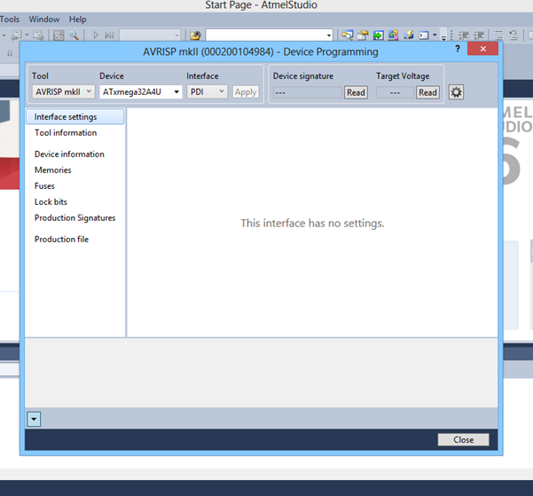
Select your programmer, the target chip and if needed the interface. Press apply and the programmer will detect your target chip. Optionally you can read the device’s signature and power supply voltage. Make sure that you downloaded the XMega zip file.
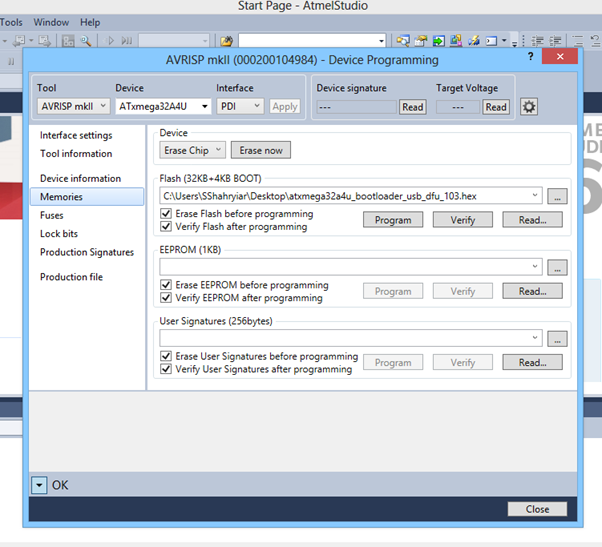
Go to the Memories option of the new window and then browse and locate the bootloader file. It is like any other MCU hex file and has the .hex extension. Press the program button after loading the bootloader hex file. This will flash the bootloader into the micro. Optionally you can verify the flash. However this is not the end of the story. We’ll have to make some changes in the fuse byte.
Now go to the Fuses option. Selecting the Fuse option will automatically make the programmer read the fuses set on it. Edit the fuses as per your need. With these settings you can change some critical hardware settings just like in any other MCU. You can configure the watchdog timer, brownout reset voltage level, etc. However whatever you do make sure that the Boot Reset fuse (BOOTRST) is programmed with BOOTLDR option. Only this will ensure that the XMega will enter into the bootloader portion of the flash memory after reset before loading the actual application coded in it. It is same as what you’ll see in an Arduino board where the bootloader runs before the application after reset. After setting the fuses as per need hit the program button to set them in your target chip. I have set the fuses as shown below:
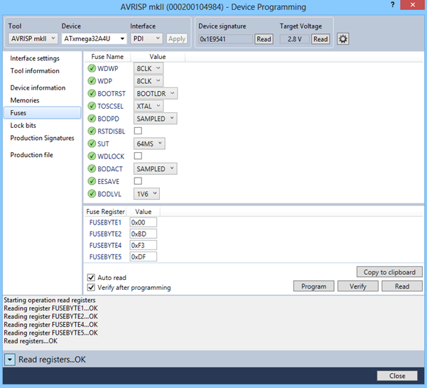
Optionally you can verify and read back the fuses that you set to check if they were set correctly.
There’s no need to set lock bits at this point if security is not as issue. Since we are just learning to play with the XMega, I don’t see any good reason to raise the security level. We are, at least this time, not making a commercially valuable good with the XMega. Thus I leave the lock bits and other options for future and up to the reader. Fuse and lock bits are retained even if the bootloader application erases the application flash.
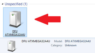
We are now done with the bootloader now. Close the AVR Studio IDE and disconnect the programmer. Install Atmel Flip. Connect the XMega to your PC via a USB port. Upon connecting the PC will attempt to install drivers for the new DFU device.

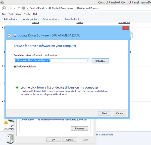
However it will not succeed to install a driver for it. You’ll have to manually install the driver. The driver for the XMega device is located in the installation location of the Atmel Flip software.
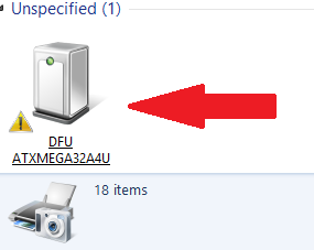
Locate and manually install the driver as shown:
Run Atmel Flip software.
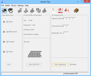
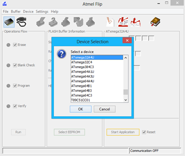
To activate the bootloader programming mode, reset the target micro while keeping PortC.3bit low. In the Flip software, select the device and select the communication medium.
Since we’ll be using the USB bootloader, we’ll select USB communication method.
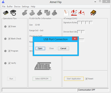
When there’s successful communication between the PC and USB DFU device the software will show USB ON at the bottom right, changing from Communication OFF.
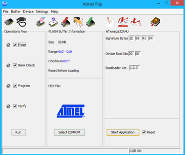
Now you can load your hex code, do blank check, erase the MCU and do other stuffs with Flip and the bootloader.
That’s all for now till the next post release. Happy playing with the XMega family.
Attachment zip file:
XMega
Author: Shawon M. Shahryiar
https://www.facebook.com/groups/microarena/
https://www.facebook.com/MicroArena
+8801970046495
|
|
Hi,
thanks for the tutorial! I’m also using an xmega32a4u, but after following these instructions I’m seeing the following under my list of USB devices:
Uknown USB Device (Device Descriptor Request Failed)
I’m not using an external crystal with my xmega, are you? I saw one in your schematic, but wasn’t sure if you had the jumpers connected. In either case, I didn’t see an option to specify the internal 32Mhz clock in the fuses settings from the datasheet. Do you think that could be the issue? or something else?
I’m also wondering how your dfu bootloader hex is different than the file supplied by atmel (I noticed they are slightly different sizes):
http://www.atmel.com/images/AVR1916.zip
thanks!
“Unknown USB Device (Device Descriptor Request Failed)” – this means that the bootloader burning had some issue or in other words the bootloader upload failed/corrupted. You must reflash the bootloader following the instructions carefully.
My board don’t have all the jumpers as in the schematic. Instead of jumpers for reset and PORTC pin 3, I used push buttons. I didn’t use any external crystal either. XMega’s internal oscillator is accurate enough.
The bootloader sizes are different but it is not an issue because I didn’t use the Atmel bootloader. Atmel bootloader will also work.
Had D+ and D- switched, working great now, Thanks!
Hello Shawon,
I’ve a blog where I talk about XMega in my series of tutorial about ASF (Atmel Software Framework): http://electro-logic.blogspot.it/p/indice-articoli-su-asf.html , it is in Italian 🙂 but you can translate it with online translator
Leonardo
Thanks for the info…. I’m intending to use MikroC Pro for AVR because with ASF things are way too easy and require less hardware abstractions…. MikroC has power libraries and is also popular amongst many students unlike other compilers….