Tutorial 5: Setting up an ESP8266 Web Server
In this tutorial, we will explore how to setup an ESP8266 web server to serve an webpage that can be displayed on a client’s browser. The client can be any other computer, smartphone, or tablet connected to the same WiFi network. The webpage will also provide an user interface to allow you to toggle an I/O pin of the ESP8266 hardware.
ESP8266 Webserver setup tutorial
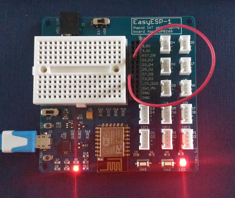
Hardware Setup
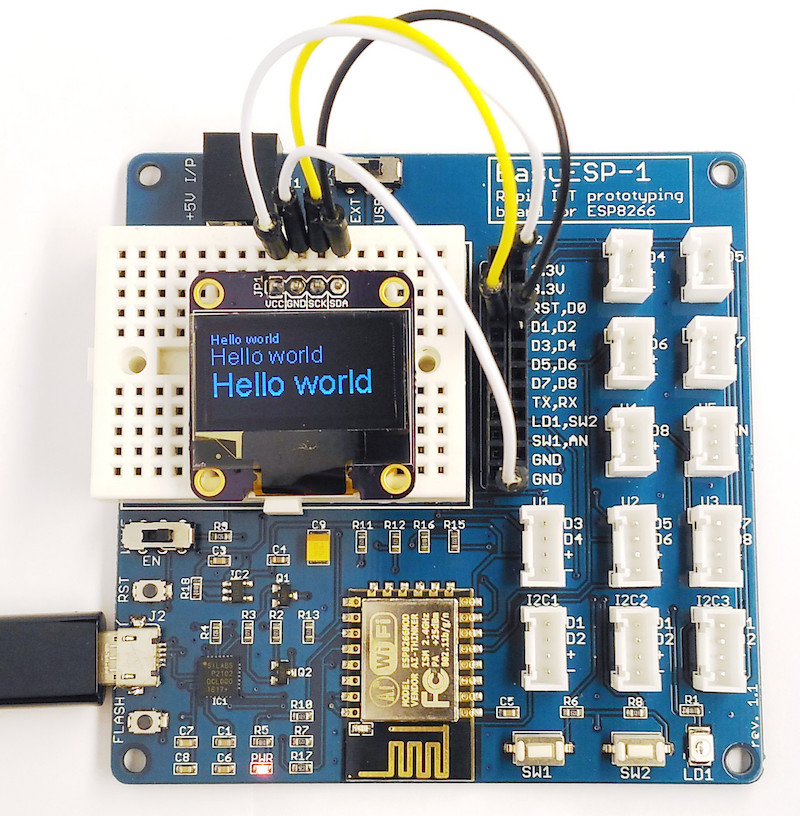
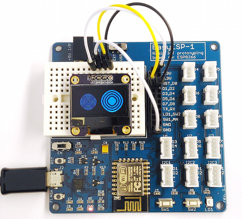
There is nothing much to do in the hardware setup of this experiment. In your EasyESP-1 board, all you need to do is to connect the LD1 pin to D1 pin using a jumper cable. This will connect the LD1 LED on board to the D1 I/O pin of the ESP8266.
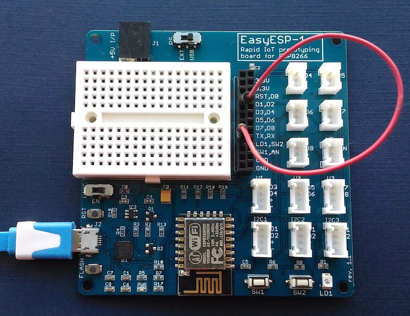
Hardware Setup
Software
As mentioned above, this tutorial illustrates how to create a standalone local web server using EasyESP-1. The web server will respond to a client’s request with a web page that will allow the user to toggle the LED connected to the D1 I/O pin. The first step to do that is to create a server object, which is done with the following statement.
WiFiServer server(80);
The server will respond to clients on port 80. You need to provide the credentials (network SSID and password) to connect to the chosen WiFi network. You can initiate the connection using WiFi.begin(ssid, password) function. Once connected to the network, you can find out the local IP address assigned to your ESP8266 using WiFi.localIP(). The complete code for this tutorial is posted below. The content of the webpage is defined in the string variable HTMLpage.
#include #include #include #include ESP8266WebServer Webserver(80); // Replace with your network credentials const char* ssid = "your network ssid"; const char* password = "password"; String HTMLpage = ""; int LED = D1; void setup(void){ HTMLpage += " |
ESP8266 Webserver Demo (Toggle LED)
"; pinMode(LED, OUTPUT); digitalWrite(LED, LOW); Serial.begin(115200); WiFi.begin(ssid, password); Serial.println(""); // Wait for connection while (WiFi.status() != WL_CONNECTED) { delay(500); Serial.print("."); } Serial.println(""); Serial.print("Connected to "); Serial.println(ssid); Serial.print("IP address: "); Serial.println(WiFi.localIP()); if (MDNS.begin("esp8266", WiFi.localIP())) { Serial.println("MDNS responder started"); } Webserver.on("/", [](){ Webserver.send(200, "text/html", HTMLpage); }); Webserver.on("/ledON", [](){ Webserver.send(200, "text/html", HTMLpage+" |
LED is ON
"); digitalWrite(LED, HIGH); delay(1000); }); Webserver.on("/ledOFF", [](){ Webserver.send(200, "text/html", HTMLpage+" |
LED is OFF
"); digitalWrite(LED, LOW); delay(1000); }); Webserver.begin(); Serial.println("HTTP Webserver started"); } void loop(void){ Webserver.handleClient(); } |
Download Webserver Tutorial code
Output
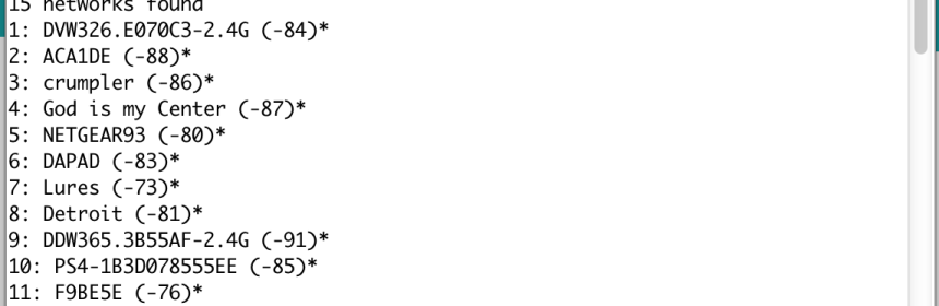
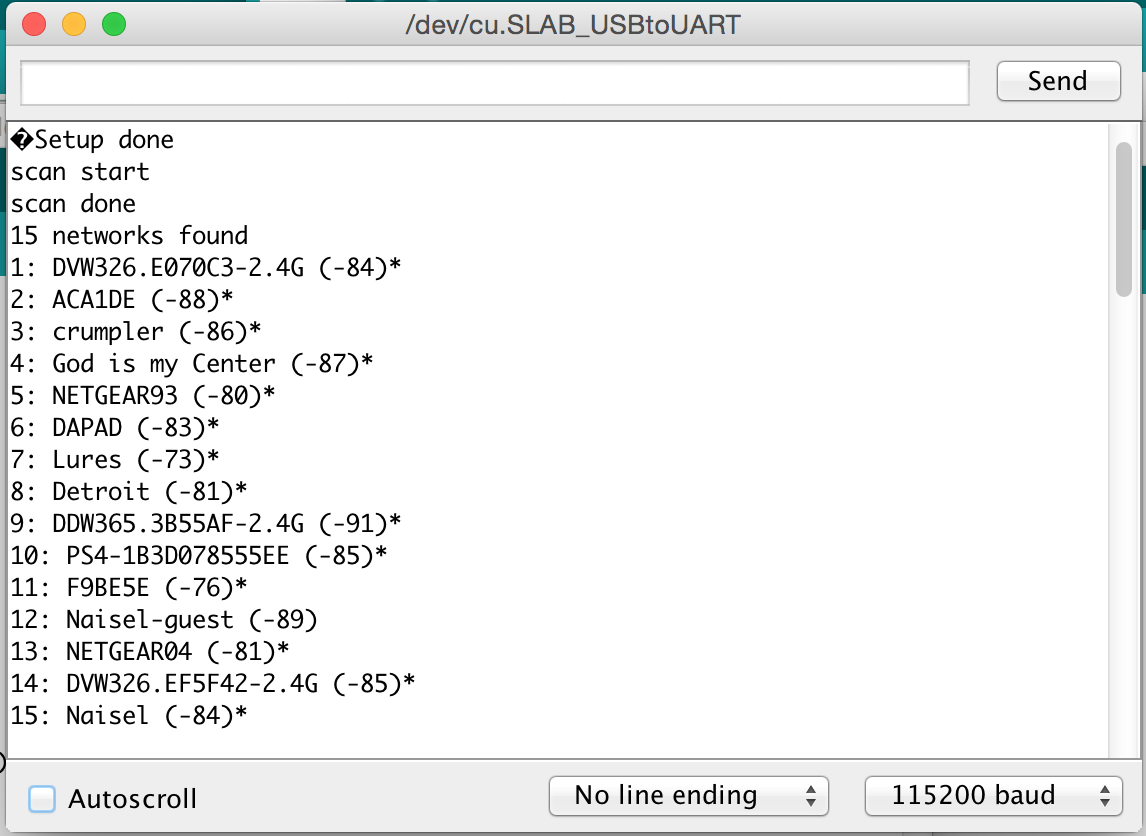
After uploading the web server code posted above (make sure you typed in your network credentials), open a Serial Monitor window for the IP address assigned to your EasyESP-1 board. If the connection to the selected WiFi network is successful, you will see the following output on the Serial Monitor window. The IP address displayed here is the IP address of the ESP8266 web server.
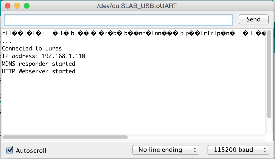
Serial Monitor terminal output
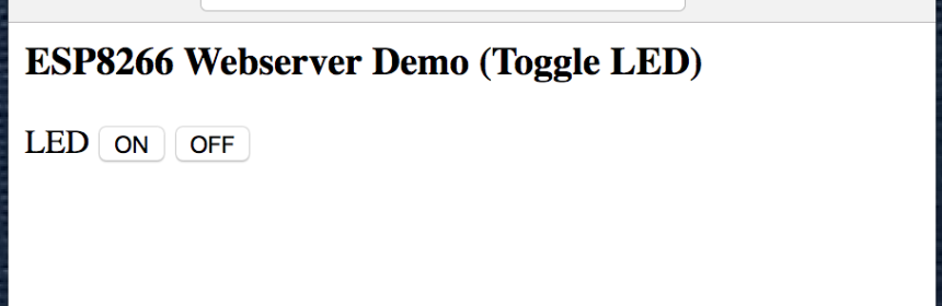
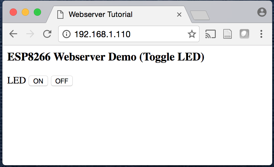
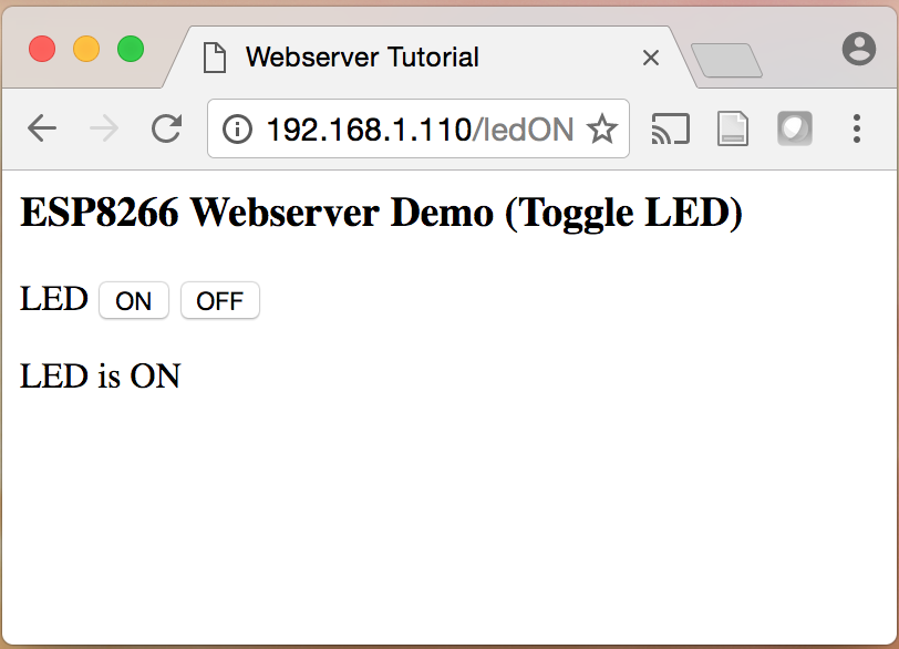
Now open a browser on any computer or tablet connected to the same WiFi network and type that IP address in the URL field and hit Go. You will see the web page served by the EasyESP-1 as follows.
Web server home page
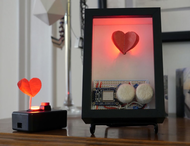
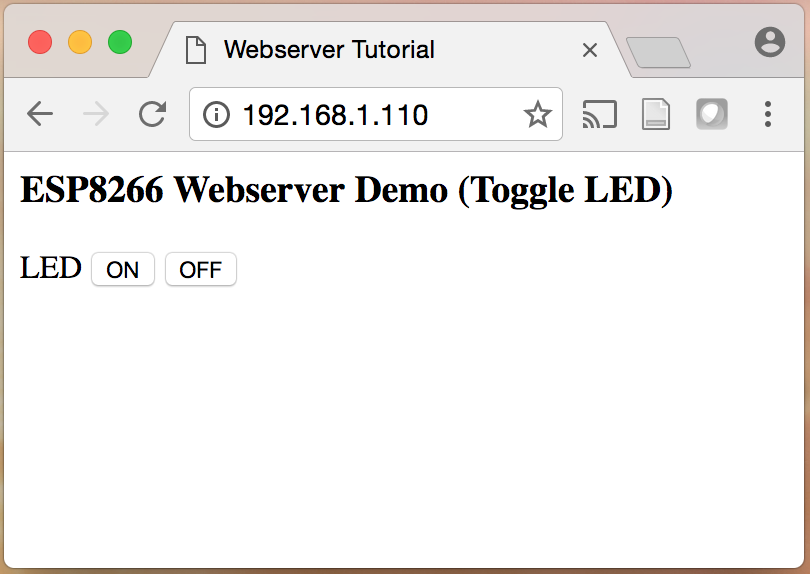
Now if you press ON button, the browser will send that info to the server, and the ESP8266 will turn ON the LED connected to D1 pin. Similarly, clicking on OFF button will turn the LED OFF.
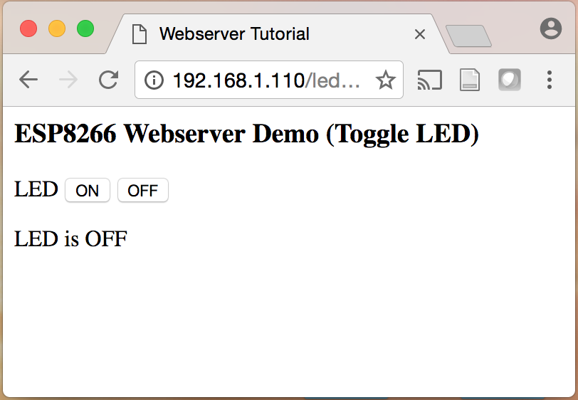
Toggling LED via web server