Lab 1: Flashing an LED

Description
Today is our first session in PIC microcontroller lab, and we will begin with an experiment that flashes an LED on and off. While this looks very simple it is the best project to start because this makes sure that we successfully wrote the program, compiled it, loaded inside the PIC, and the circuit is correctly built on the breadboard.
In this lab session we will connect an LED to one of the port pin of PIC16F688 and flash it continuously with 1 sec duration.
Required Theory
You must be familiarized with,
- digital I/O ports (PORTA and PORTC) of PIC16F688
- direction control registers, TRISA and TRISC
- special function registers CMCON0 and ANSEL
If you are not then please read this first: Digital I/O Ports in PIC16F688.
Circuit Diagram
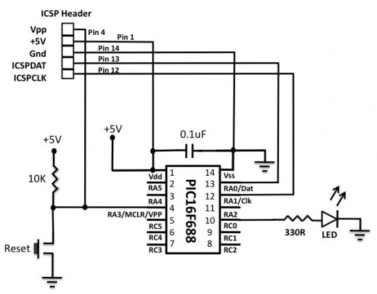
To our basic setup on the breadboard (read Getting Ready for the First Lab), we will add a light-emitting-diode (LED) to port pin RC0 (10) with a current limiting resistor (470 Ohm) in series. The complete circuit diagram is shown below.


