chipKIT Project 4: Digital light meter
|
|
A light meter is used to measure the intensity of illumination in a given area. It is widely used in schools, warehouses, factories, hospitals, office buildings, museums, art-galleries, parking garages, stadiums, and many more, to measure and maintain proper lighting levels. The intensity of illumination is usually expressed in Lux or foot-candles. As the 4th project in our chipKIT tutorial series, today we are going to build a digital light meter using the chipKIT Uno32 board and the BH1750 digital light sensor. This project uses Digilent’s chipKIT Basic I/O shield for displaying the measured light intensity in Lux, foot-candles, and Watts/m^2 units.
Digital light meter using chipKIT Uno32
What do we need?
In order to build this project, we will need the following things.
- chipKIT Uno32 board
- chipKIT Basic I/O Shield
- BH1750FVI digital light sensor
- Breadboard with a few jumper wires
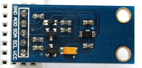
This project uses the BH1750FVI sensor (datasheet) to measure the intensity of surrounding light. BH1750FVI is a calibrated digital sensor IC that converts the incident light intensity into a 16-bit digital number (0-65535). The 16-bit output can be converted to Lux by simply dividing it by 1.2. Thus it can measure the maximum ambient light intensity of 65535/1.2 = 54612 Lux. The spectral response function of the sensor is approximately close to that of the human eye. The sensor supports the I2C interface. The 7-bit I2C address of the sensor can be set to 0×23 by grounding the ADDR pin, and to 0x5C by connecting ADDR to VCC. It is grounded by default through a pull-down resistor on board.
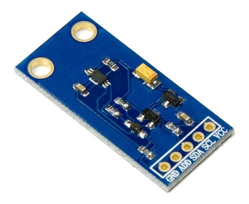
BH1750FVI sensor board
Circuit setup
The setup for this project is very simple. The JP6 and JP8 header jumpers on the Uno32 board are placed in the RG3 and RG2 position in order to use the A4 and A5 pins pins for I2C operation. The chipKIT I/O shield is then inserted on the top the Uno32 board. The BH1750FVI sensor board is plugged into the breadboard and is powered through the 3.3V power supply from the I/O shield. The SDA and SCL signal lines are connected to the analog input pins A4 and A5, respectively.
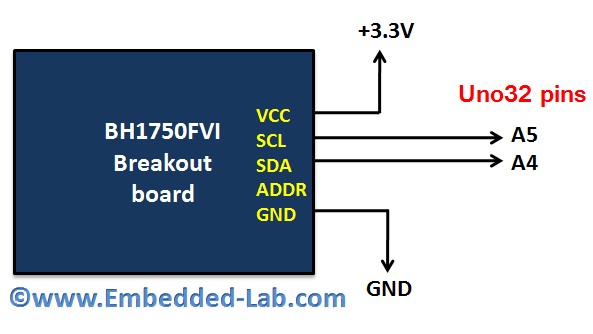
BH1750FVI connections
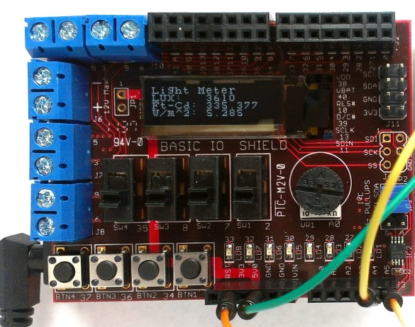
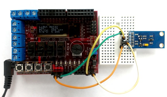
The following picture shows the complete setup of this project.
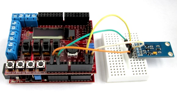
Digital light meter project setup
chipKIT sketch
A firmware has been developed to display the measured light intensity on the OLED screen of the I/O shield. The display portion of the sketch uses the chipKIT I/O Shield library provided by Digilent. The light intensity is displayed in Lux, foot-candles, and watts/m^2 computed at the center of the visible spectrum, which is ~555nm. The following equations are used to convert Lux into foot-candles and watts/m^2.
Foot-candles = Lux/10.764
Watts/m^2 = Lux/683.002 (At ~555 nm wavelength)
Download the complete project sketch
Output
Upload the light meter sketch (download link provided above) to your Uno32 board and your light meter is ready to rock. Now you have your own device to check if you have a proper illumination level at your work space. You can move the sensor to face at multiple directions to see the differences in the lighting level in those directions. The measurement is set to refresh in every 3 seconds but you can modify it in the sketch to take samples at faster rates.
Light meter in action
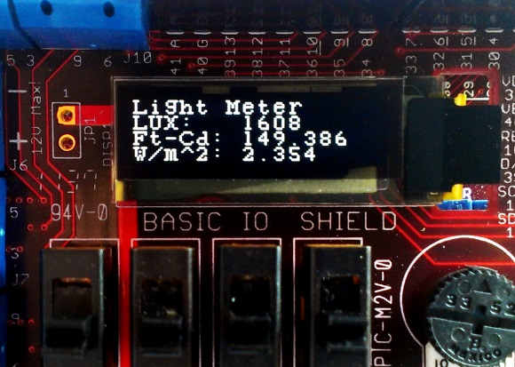
Closer look of the display
|
|
I was always getting ‘54612 lux’ measurments. It was mystery, until I found out, that I had to connect my SCL and SDA pins to dedicated 20th and 21st pins on Arduino MEGA 2560.
i need full project
i want full project report for this because i have doubts