STM32 External Interrupt
|
|
In my earlier post on STM32 GPIOs I showed how to flash a LED with variable delay times. That example was based on polling method where the code continuously monitored the logic state of a GPIO input pin attached to a push button to determine the delay amount. Obviously that won’t be an efficient technique when a program will be of a considerable size and complexity. This is simply so because the CPU will have to check the GPIO’s logic state every time the super-loop (while (1) loop in the main function) repeats and the push button will also not be responsive during the software delay function calls. Thus the overall performance is poor and not real-time. To get rid of these issues, we’ll need to use external interrupts – a vital feature in every common microcontroller.
STM32F1xx series are ARM Cortex M3 based MCUs. The Cortex M3 based MCUs have a sophisticated and yet easy to use interrupt system called the Nested Vectored Interrupt Controller (NVIC). It ensures low latency and high performance. There are several features of the NVIC and these are handled by the compiler. Our job is simply to enjoy the lightning fast interrupt responses owing to the NVIC. In many MCUs’ interrupt system, interrupt priority can be set and Reset has the highest interrupt priority over anything else. The same things go for STM32s too. However at present I’m not going to go that deep as that’s not needed for now. In some upcoming post may be I’ll discuss the NVIC in details. As per STM32’s reference manuals for more information on exceptions and NVIC programming read Chapter 5 Exceptions and Chapter 8 Nested Vectored Interrupt Controller of the ARM Cortex-M3 Technical Reference Manual. There are other interrupts that are related to RTC, timer, etc. We won’t also look into them in this post. We will learn about them when we learn about the related hardware with them.
Internal Structure
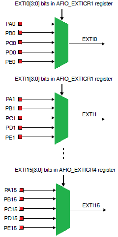
There are 16 external interrupt lines with separate interrupt vector addresses that are connected with GPIO pins. Thus there are 16 multiplexers connected to the NVIC and are named as External Interrupt/Event Controllers, EXTI0, EXTI1, etc. up to EXTI15. We know from our previous encounters with STM32s that STM32 GPIOs are 16bit wide and so we can see the reason why there are 16 lines of EXTI. GPIO pins of the same order are grouped together and connected to an EXTI channel. For instance EXTI1 is connected to PA1, PB1, etc. and not like PA0, PA1, etc. This is why at any given instance we can have an external interrupt in only one of connected GPIO pins of that EXTI mux. For example when we need to use EXTI2, we can use either PA2, PB2, PC2, etc. but not PA2, PB2, etc. simultaneously. Thus an entire GPIO port or port pins from different GPIO ports can be configured as external interrupts. Interrupts in all pins is an unnecessary stuff. We can also decide when to sense an interrupt – on rising/falling or both edges. All these settings are separately stored, allowing high flexibility.
The EXTI lines 0 – 4 are individually and directly connected to the NVIC interface while the remaining higher order EXTI lines are grouped into two – one ranging from EXTI 5 to 9 and the other from 10 – 15. The upper EXTI pins are thus not individually and directly connected to the NVIC. Owing to this EXTI 0 – 4 have separate unique interrupt vector addresses while the rest have two separate interrupt vector addresses.
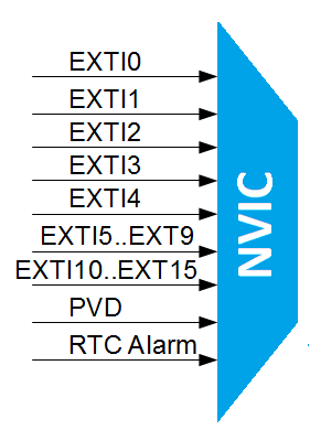
This grouping doesn’t have too much serious issues with normal external interrupt uses and in fact I found out that it is rather useful as I don’t have to code for separate interrupt routines. A good example of its use is with an interface. One such routine can take care of digital inputs coming from a keyboard or joystick. In my example code this is what I demonstrated.
Registers
The interrupt system of STM32 is not too much complex and only a few registers need to be taken care of after setting GPIO pins. The first thing to do is to setup which EXTI lines to use and which port pins to use.
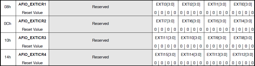
AFIO_EXTICRx registers determine this. However please note that we must enable AFIO functionality from RCC_APB2ENR register first before can use it. If you can remember from my post on GPIOs, I stated that in the code the very first thing we do is simply enable the peripherals we need by setting appropriate RCC_APB bits. As seen in the register map above EXTI lines are grouped as 4 bits and value of these 4 bits select port pins. 0000 means PA[x] pin, 0001 PB[x] pin and so on.
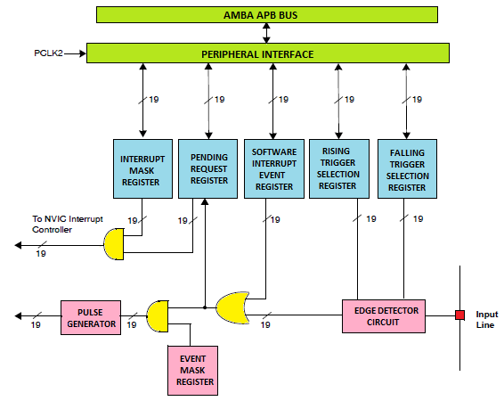
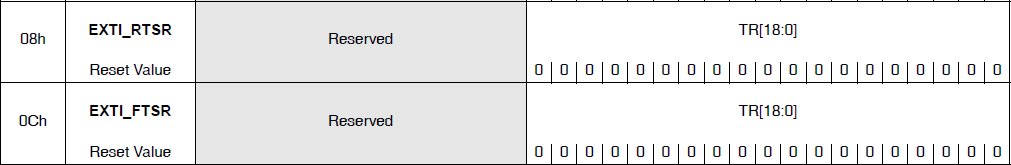
Secondly we need to select the edge needed to invoke an interrupt. Triggering edge can be rising, falling or both. This is done be setting the required bits of EXTI_FTSR and EXTI_RTSR registers. By default the bits in these registers are cleared and so no edge is selected after reset. To select falling edge required EXTI_FTSR bits are set. Similarly to select rising edge required EXTI_RTSR bits are set. To detect both edges both register are set.
The next thing to do is to unmask only those interrupts that we need. This is done by setting needed bits of the EXTI_IMR register.

Finally we need to set the NVIC in order to enable interrupt. We just need to specify the sources of interrupt request. In MikroC for ARM compiler this process is simply done with just two lines of code. We also need an interrupt service routine more commonly known as ISR function to tell the MCU what to do during interrupt. Inside the interrupt we need to check which interrupt is pending by reading the interrupt request pending register – EXTI_PR. After reading the EXTI_PR bit that caused the interrupt we have to clear the pending request by setting that bit.
Demo Code
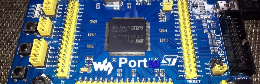
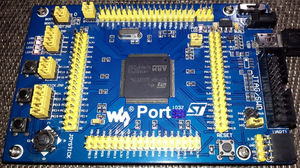
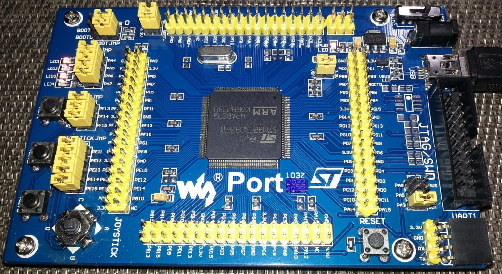
The code that I programmed for this demo is pretty simple. I used a Port 103Z Waveshare STM32F103ZET6 development board – http://www.wvshare.com/product/Port103Z.htm.
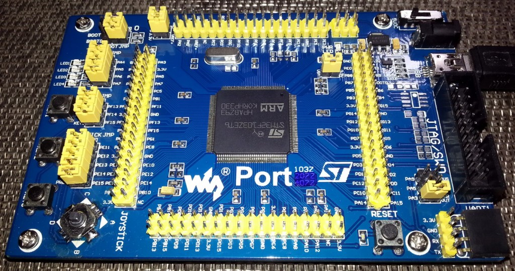
The code simply monitors the inputs from the joystick attached in the development board using external interrupt. Waveshare Electronics cleverly connected the joystick pins to PE11 – PE15. These are the pins that are associated with EXTI15_10 group. Thus each of these pins invoke a common interrupt request – the same thing I told about taking inputs earlier. Thanks to Waveshare for this arrangement as it made my work much easier. In the Port 103Z development board, there are four user LEDs that are connected to PA4 – PA7 by default using jumpers. I used these LEDs to check the output. When the code starts executing all of the board LEDs are turned on at first. When the joystick is pressed towards a direction only one LED will start blinking. Since there are four directions, the four LEDs will blink separately to denote four direction. When the center button of the joystick is pressed the LEDs will light by oscillating in a to-and-fro manner. The main function only deals with LED blinking. The ISR only deals with the joystick inputs. The LEDs respond as fast as an input is detected, forming a pretty straight real-time system.
#define dly 60 //Delay size
unsigned char s = 0;
void external_interrupt() //ISR function
iv IVT_INT_EXTI15_10 //Interrupt Vector Address
ics ICS_AUTO //Save interrupt context
{
if((EXTI_PR & 0x00000800) != 0) //Check if PE11 has trigger the interrupt
{
s = 1;
EXTI_PR |= 0x00000800; //Clear PR11
}
if((EXTI_PR & 0x00001000) != 0) //Check if PE12 has trigger the interrupt
{
s = 2;
EXTI_PR |= 0x00001000; //Clear PR12
}
if((EXTI_PR & 0x00002000) != 0) //Check if PE13 has trigger the interrupt
{
s = 3;
EXTI_PR |= 0x00002000; //Clear PR13
}
if((EXTI_PR & 0x00004000) != 0) //Check if PE14 has trigger the interrupt
{
s = 4;
EXTI_PR |= 0x00004000; //Clear PR14
}
if((EXTI_PR & 0x00008000) != 0) //Check if PE15 has trigger the interrupt
{
s = 5;
EXTI_PR |= 0x00008000; //Clear PR15
}
}
void setup()
{
RCC_APB2ENR = 0x00000045; //Enable AFIO, GPIOA and GPIOE
GPIOA_CRL = 0x22220000; //Set GPIOA 4 - 7 as 2MHz Push-pull outputs
GPIOE_CRH = 0x88888000; //Set GPIOE 11 - 15 as digital inputs
GPIOE_ODR = 0x0000F800; //Enable pullups for Joystick / PE pins
GPIOA_ODR = 0x000000F0; //Set LED / PA 4 - 7 pins high
AFIO_EXTICR3 = 0x00004000; //Select PE lines for EXTI interfaces
AFIO_EXTICR4 = 0x00004444; //Select PE lines for EXTI interfaces
EXTI_FTSR = 0x0000F800; //Select falling edge interrupt
EXTI_IMR = 0x0000F800; //Unmask bits 11 - 15 for interrupt on those lines
NVIC_IntEnable(IVT_INT_EXTI15_10); //Enable NVIC interface
EnableInterrupts(); //Enable global interrupt
}
void main()
{
setup(); //Initialize MCU
while(1) //Super loop
{
switch(s)
{
case 1:
{
GPIOA_ODR = 0x00000010; //Turn PA4 LED high only
delay_ms(dly); //Wait for some time
GPIOA_ODR = 0x00000000; //Turn off all LEDs
delay_ms(dly); //Wait for some time
break;
}
case 2:
{
GPIOA_ODR = 0x00000020; //Turn PA5 LED high only
delay_ms(dly); //Wait for some time
GPIOA_ODR = 0x00000000; //Turn off all LEDs
delay_ms(dly); //Wait for some time
break;
}
case 3:
{
GPIOA_ODR = 0x00000040; //Turn PA6 LED high only
delay_ms(dly); //Wait for some time
GPIOA_ODR = 0x00000000; //Turn off all LEDs
delay_ms(dly); //Wait for some time
break;
}
case 4:
{
GPIOA_ODR = 0x00000080; //Turn PA7 LED high only
delay_ms(dly); //Wait for some time
GPIOA_ODR = 0x00000000; //Turn off all LEDs
delay_ms(dly); //Wait for some time
break;
}
case 5:
{
GPIOA_ODR = 0x00000050; //Toggle LEDs
delay_ms(dly); //Wait for some time
GPIOA_ODR = 0x000000A0; //Toggle LEDs
delay_ms(dly); //Wait for some time
break;
}
}
}
}
Video Link: https://www.youtube.com/watch?v=0z7kmKoyCJs
Finally a word of caution, never use an input pin without an internal or external pull-up or pull-down resistor unless you want to end up in a mess. Forgetting to do this yield in undesired results. I found that the GPIOs are so sensitive that they can detect the presence of my hand or even a metal tool a few centimeters away. I was puzzled on one such occasion only to find out that I forgot about pull-up resistors for input pins.
Happy playing with STM32 ARMs.
Repository: https://github.com/sshahryiar/STM32-Tutorials
Author: Shawon M. Shahryiar
https://www.youtube.com/c/sshahryiar
|
|
Instead of using NVIC_IntEnable(IVT_INT_EXTI15_10); EnableInterrupts(); I wish to directly access the ISER register in NVIC. Can you explain how to map the ISER bits to the corresponding interrupt line?
Good intro.
Question is about triggering on both leading and trailing edges. In the ISR, how will you detect which was triggered? Read the port value?
thanks, srini
Yeah read the input port pin value in the ISR and check its state to find out if it is responding to a rising or falling edge….