TrH Meter: A DIY indoor thermometer plus hygrometer with adaptive brightness control implemented to 7-segment LED displays
|
|
This project is about building a microcontroller-based digital room thermometer plus hygrometer that displays temperature and relative humidity on 4 large (1 inch) seven segment LED displays which adjust their brightness level according to the surrounding illumination. It consists of a closed loop system that continuously assesses ambient light condition using an inexpensive light-dependent resistor (LDR) and uses that information to adjust the brightness of the display. An inexpensive DHT11 sensor is used to measure temperature and relative humidity. The microcontroller used in this project is PIC16F688, and it runs at 4 MHz clock generated from its internal source. A separate display driver chip (MAX7219) is used to control and refresh the display data on the seven segment LEDs.

TrH Meter: A DIY indoor thermometer plus hygrometer
Why do we need adaptive brightness control?
Auto-adjusting the brightness of the seven segment LED displays not only saves power but also enhances the readability in all ambient lighting conditions. Many smartphones, HDTVs, PDAs, tablets, and computer screens now come with this feature. It basically dims the display in a dark environment and is still readable and eye-soothing. Similarly, when the ambient light level goes up, it brightens the display to enhance the readability. This project displays indoor temperature and relative humidity on large 1 inch seven segment LEDs that automatically adjust the brightness to be in balance with the light condition in the room. So, if you put this meter in your bedroom, you won’t have to worry about turning it off during nighttime. It will automatically dim low enough to not to disturb your sleep, while maintaining the readability.
Circuit diagram
To make it easy to explain, I have divided the complete circuit diagram into 3 parts: Power supply unit, Microcontroller and sensor unit, and Display driver unit.
The power supply unit consists of a LM7805 regulator IC to derive regulated +5V power supply from a 9-15V DC wall adapter. The complete power supply unit circuit diagram is shown below. LED1 is a power-on indicator LED.

Regulated +5V power supply unit
The following circuit diagram shows connections of the DHT11 sensor and the photoresistor (also called light dependent resistor or LDR) to the PIC16F688 microcontroller. DHT11 is a low cost digital sensor for measuring temperature from 0-50 °C with an accuracy of ±2°C and relative humidity ranging from 20-95% with an accuracy of ±5%. The sensor provides fully calibrated digital outputs and has got its own proprietary 1-wire protocol for communication. I have described more about this sensor and its communication protocol in Measurement of temperature and relative humidity using DHT11 sensor and PIC microcontroller. The PIC16F688 uses the RC4 I/O pin to read the DHT11 output data. Note that R7 serves as the pull-up resistor required for the data pin of the DHT11 sensor. The S2 switch in the circuit diagram is to select between degree Fahrenheit (°F) and degree Celsius (°C) unit for temperature display. When the switch is open, the RC3 pin is pulled low by default, and the temperature is displayed in °F scale. In order to chose °C scale, the RC3 pin should be pulled high, which happens when S2 is closed.
Next, the photoresistor (R5) and R4 construct a voltage divider network as shown in the circuit. The analog voltage across R4 increases proportionally with the amount of light falling on the photoresistor. The resistance of a typical photoresistor is less than 1 K? under bright lighting condition. Its resistance could go up to several hundred K? under extremely dark condition. Therefore, for the given setup, the voltage across the R4 resistor can vary from less than 0.1V (under dark condition) to over 4.0V (under very bright illumination). The PIC16F688 microcontroller reads this analog voltage through its AN2 (RA2) ADC channel to determine the surrounding illumination level.

Microcontroller circuit
The display unit consists of a MAX7219 chip that can directly drive up to eight 7-segment LED displays (common cathode type) through a 3-wire serial interface. Included on the chip are a BCD decoder, multiplex scan circuitry, segment and digit drivers, and an 8×8 static RAM to store the digit values. The segment current for all LEDs is set through only one external resistor connected between the ISET pin and power supply. The device also provides 16 level brightness control through software using its internal pulse-width modulator. To learn more about the MAX7219 device, read my previous article Serial 4-digit seven-segment LED display. In this project, the RC0, RC1, and RC2 I/O pins of PIC16F688 are used to drive the DIN, LOAD, and CLK signal lines of the MAX7219.

Display circuit
Here’s the complete project circuit setup on a general purpose perforated prototyping board.

Circuit made on a general purpose perforated prototyping board

Complete setup
Software
The PIC firmware is developed in C and compiled with mikroC Pro for PIC compiler version 5.30. The subroutines for initializing the MAX7219 and sending display data bytes are written in a simple and understandable way so that they can be easily implemented with any other programming language, if required. The MAX7219 allows display brightness to be controlled through software by an internal pulse-width modulator (PWM). The PWM output is controlled by the lower nibble (D3-D0) of the intensity register (address 0x0A) and allows 16 brightness levels. The zero nibble value sets the display intensity to minimum, whereas all nibble bits set to 1 (0x0F) selects the maximum intensity level for the display. For auto-brightness control, the 10-bit ADC count (0-1023) corresponding to the photoresistor output voltage is scaled down to 0-19 by dividing the count by 50 (20 brightness levels between 0-1023). Then a look-up table is used to map the scaled brightness levels to appropriate nibble values for the intensity control register of the MAX7219. The temperature is displayed in Fahrenheit (°F) scale if RC3 is pulled low, and in Celsius (°C) scale if RC3 is high. The relative humidity measurement is shown in percentage (P). The microcontroller alternately switches the display data between temperature and relative humidity.
// Define Soft-SPI connections for LED display #define MOSI_Pin RC0_bit #define CS_Pin RC1_bit #define CLK_Pin RC2_bit // Define Data pin for DHT11 #define Data RC4_bit #define DataDir TRISC4_bit #define FC_Select RC3_bit // Fahrenheit or Celcious select unsigned short TOUT = 0, CheckSum, i, check, u, NumSamples; unsigned short T_Byte1, T_Byte2, RH_Byte1, RH_Byte2; unsigned long int brightness=0x0b; unsigned int counter = 0, TempF, TempC, RH, ADC_OP, TempSum, RHSum; //Brightness look-up table unsigned short Brightness_Table[21] = {0, 1, 2, 3, 3, 4, 4, 5, 5, 6, 7, 8, 9, 10, 11, 12, 12, 13, 14, 15, 15}; void SPI_Write_Byte(unsigned short num){ unsigned short t, Mask, Flag; CLK_Pin = 0; Mask = 128; for (t=0; t> 1; } } void MAX7219_INIT() { // Disable Shutdown mode CS_Pin = 0; // CS pin is pulled LOW SPI_Write_Byte(0x0C); // Select Shutdown register SPI_Write_Byte(0x01); // Set D0 bit to return to normal operation CS_Pin = 1; // CS pin is pulled HIGH // Set BCD decode mode for digits DIG1-DIG3, and DIG5-DIG7 CS_Pin = 0; // CS pin is pulled LOW SPI_Write_Byte(0x09); // Select Decode Mode register SPI_Write_Byte(0b00001100); // Disable BCD mode for digits DIG0, DIG1 CS_Pin = 1; // CS pin is pulled HIGH // Set display brighness CS_Pin = 0; // CS pin is pulled LOW SPI_Write_Byte(0x0A); // Select Intensity register SPI_Write_Byte(brightness); // Set brightness CS_Pin = 1; // CS pin is pulled HIGH // Set display refresh CS_Pin = 0; // CS pin is pulled LOW SPI_Write_Byte(0x0B); // Select Scan-Limit register SPI_Write_Byte(0x03); // Select digits DIG0-DIG3 CS_Pin = 1; // CS pin is pulled HIGH // Enable Display-Test CS_Pin = 0; // CS pin is pulled LOW SPI_Write_Byte(0x0F); // Select Display-Test register SPI_Write_Byte(0x01); // Enable Display-Test CS_Pin = 1; // CS pin is pulled HIGH Delay_ms(1000); // Disable Display-Test CS_Pin = 0; // CS pin is pulled LOW SPI_Write_Byte(0x0F); // Select Display-Test register SPI_Write_Byte(0x00); // Disable Display-Test CS_Pin = 1; // CS pin is pulled HIGH } void Display_Value(unsigned int j, unsigned short k){ CS_Pin = 0; // CS pin is pulled LOW SPI_Write_Byte(4); // Send thousands digit SPI_Write_Byte((j/100)%10); CS_Pin = 1; // CS pin is pulled HIGH CS_Pin = 0; // CS pin is pulled LOW SPI_Write_Byte(3); // Send hundreds digit SPI_Write_Byte(((j/10)%10)); CS_Pin = 1; // CS pin is pulled HIGH CS_Pin = 0; // CS pin is pulled LOW SPI_Write_Byte(2); // Send tens digit if(k 40) num |= 1<40us, Data is 1 } return num; } void interrupt(){ if(PIR1.TMR1IF){ TOUT = 1; T1CON.TMR1ON = 0; // stop timer PIR1.TMR1IF = 0; // Clear TMR0 interrupt flag } } void Display_Brightness(){ ADC_OP = ADC_Read(2); Brightness = ADC_OP/50; CS_Pin = 0; // CS pin is pulled LOW SPI_Write_Byte(0x0A); // Select Intensity register SPI_Write_Byte(Brightness_Table[brightness]); // Update brightness CS_Pin = 1; // CS pin is pulled HIGH } void Wait_Nsec(){ Delay_ms(3000); } void main() { ANSEL = 0b00000100; // RA2/AN2 is analog input CMCON0 = 0x07 ; // Disbale comparators TRISC = 0b00001000; // PORTC All Outputs except RC3 TRISA = 0b00001110; // PORTA All Outputs, Except RA3 and RA2 INTCON.GIE = 1; //Enable global interrupt INTCON.PEIE = 1; //Enable peripheral interrupt // Configure Timer2 module PIE1.TMR1IE = 1; // Enable Timer2 interrupt T1CON = 0; // Prescaler 1:1, and Timer2 is off initially PIR1.TMR1IF =0; // Clear TMR INT Flag bit TMR1H = 0; TMR1L = 0; MAX7219_INIT(); // initialize max7219 if(!FC_Select) Display_Value(0, 0); if(FC_Select) Display_Value(0, 1); do{ NumSamples = 0; TempSum = 0; RHSum = 0; for (u=0; u |
The PIC16F688 microcontroller runs at 4.0 MHz internal clock. The MCLR and Power-Up Timer (PWRT) are both enabled.
Output
The project was tested under different indoor lighting conditions, varying from very dark to very bright. The display was found equally well readable and eye-soothing in all the different conditions. I have put it in my bedroom and at night the display automatically dims low enough to not disturb the sleep, while I can still read the temperature and humidity readings in the dark.

Relative humidity in percentage (P)
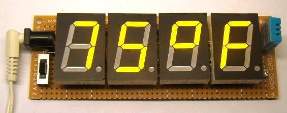
Temperature displayed in Fahrenheit (F)
Update
I am now selling a complete kit of this project (with pre-programmed PIC16F688 microcontrollers) on Tindie. If you are interested, you can order it from here:
Tindie order link: https://www.tindie.com/products/rajbex/pre-order-trh-meter-kit-3/
The PCB version uses the same circuit diagram as described above except it uses AMS1117-5.0 regulator IC instead of LM7805. Here’s a picture of an assembled project board. The soldering instructions for this kit are available here.

Assembled project board
|
|
Hello,
Does anyone know how much
current this project requires?
Thx,
Grant
Thank you very much for the project.
I made.Works well.
can you explain a bit on how the PIC RC2 provides clock for the MAX?
The clock is generated at RC2 through software by bit-banging the I/O pin.
The Display of four seven segment is Common anode Our Commo Katode?
Thanks and congratulation for excelent Project…
It is mentioned in the article. Read carefully.
Hello R-B,
can you please help me how 0x4E Prints C Symbol ? Please explain me. thanks…
awesome project… grt…..
could you send me the schematic diagram for this..
You could have saved a lot of expense by going with a cheap LCD.
really you did a very awesome project
can you send me please the isis shematic?
i wish if i can realize this project
thx
Hi Raj!
Can you provide an explanation for photocell ADC_Read, command?
i would like to do a nightlight using a photocell with pic16f688
thank you very much!
marC:)