00 to 99 minute timer using PIC16F628A microcontroller
|
|
Last week I was browsing my old backup hard drive and I found a source code for a very simple PIC based digital timer that I made a couple of years ago. The actual hardware of the project isn’t with me anymore. I might have lost it when I moved from my old apartment into my new home. However, I thought this might be a good practice project for beginners and so I am sharing it here. I am not going to build it from scratch again; I will rather demonstrate it using my DIY PIC16F628A breadboard module and I/O board. The complete circuit diagram along with the firmware developed using mikroC Pro for PIC compiler is provided in the article.

0-99 minute timer
Circuit diagram
As I mentioned earlier, the microcontroller used in this project is PIC16F628A running at 4.0 MHz clock using an external crystal. An HD44780 based 16×2 character LCD is the main display unit of the project where you can watch and set the timer duration using tact switch inputs. There are three tact switches connected to RB0 (Start/Stop), RB1 (Unit), and RB2 (Ten) pins. You can select the timer interval from 0-99 min using Unit and Ten minute switches. The Start/Stop switch is for toggling the timer ON and OFF. When the timer gets ON, a logic high signal appears on the RA3 pin, which can be used to switch on a Relay. The circuit diagram of this project is described below.

0-99 minute timer circuit
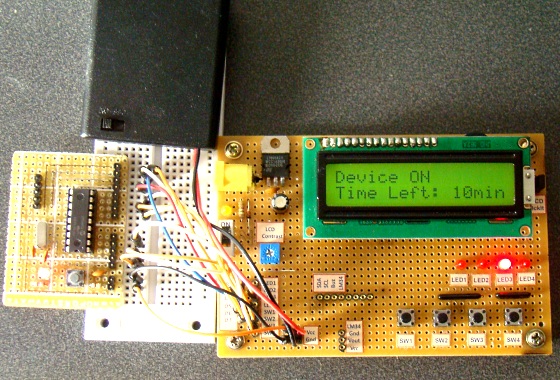
I am using my self-made breadboard module for PIC16F628A and experimenter’s I/O board here to demonstrate this project. Since there is no relay switch in the I/O board, I am connecting the timer output (pin RA3) to an LED. When the timer starts, the LED is turned ON. As the timer duration is elapsed, the LED is turned OFF.

Circuit setup
Operation of the Timer
When the device is powered ON, the microcontroller initializes the LCD display and shows the following message. The timer is initially OFF and so does the LED or relay, whichever is connected to RA3 pin.

Message displayed at power on
You can set time duration between 00-99 min (in step of 1 min) using the Unit and Ten tact switches. Each switch press will increment the corresponding time digit.

Setting timer minute
When the desired time is set, press the Start/Stop switch to turn ON the timer. The RA3 pin goes high (LED glows) and the count down begins. When the timer is ON, the remaining time is also shown on the LCD screen. When the time elapsed, the timer stops and the LED turns OFF. You can interrupt and stop the timer at anytime by pressing the Start/Stop switch once more.

Displaying the left over time on LCD
Software
The firmware for PIC is developed using mikroC Pro for PIC compiler. The use of Timers are avoided for simplicity. The time delays are created using the Delay_ms() function of mikroC, which seems to give reasonably accurate timing delays.
Download mikroC source code and HEX file
For a more advanced digital timer switch, read my another project: Programmable digital timer.
|
|
Hi Rajendra,
I have ported this code into a PIC16F886 but the SS_Select is seems to be not working.
If the timer is ON and if pressing the SS_Select button the timer should STOP and the message: “Timer is OFF” should show.
I seem to have trouble here..
Any clues as to why?
Appreciate any help.
//regards,Gonzo
sir is their possible to start timer without using any button actually u want to set time of 6 hours and than time reset for my project so pplz help me
Sir, I have tried your code ,,but your code have a little mistake, when i am set timer your code take 15sec delay after every minute left..pls tell me how to solve it this problem.
Sir, I have tried your code ,,but your code have a little mistake, when i am set timer your code take 15sec delay more after every minute left. pls tell me how to solve this problem.
How to start a Timer of 10s when pic is turned ON,and after counting make a port high ???
pls help…..
Respected sir,
Am Abhimanyu M,3rd year b.tech student at COLLEGE OF ENGINEERING CHENGANNUR. we have mini project on this sem (s6)
pls help us…
Our project is RFID ACCESS CONTROL SYSTEM
we are using PIC miro-controller (16F876A 28pin DIP )
We want to know about the programming of TIMER in PIC.
When PIC is turned ON, RFID reader is also turned ON.
If NO RFID card is detected with in 10seconds after PIC is turned ON,
a led/alarm should TURN ON (by giving high to any port pin)
How can we do this??
Can we start a Timer of 10s when pic is turned ON,and after counting make a port high ??? if YES how?????
pls help…..
we are running out of time …pls help……….
with HOPE
please could you send me the c-code for this project on my mail.
You can download from the software section at the bottom.
please would you send the c-code for this project .It will help us a lot.
Hi Sir,
How can use this circuit for 120v ac or 230v AC?
Sorry, it was my bad, the reset switch made constant contact therefore it reset every millisecond
Could you please send me an updated hex file to my email. This one seems to be broken
Dear Sir,
will it work every 10mintus ON and 5 mintues OFF automatically
Hex file not working,all projects on net with this schematic don´t work either a compiler error source or no fuse setings for persons with no knowledge burn their project to pic, Also micro pic c and matlab ide with c Compiler ,refuses to compile without errors…
Was good that authors give a little more info and correct this issues….
Regards
Hi R-B.
Please can you tell me the fuse settings for the hex file of this timer ?.
Thank you.
its very nice project, nice working, if its char 4digit for microsecond , so what the programming. sir please help me.
The hex file that you give, its not working……..ohh
sir the hex is not working sir please correct hex file re send my mail repaly sir
Dear sir Your timer 100% work it vary good but I want set time continue working timer plz help me thank you.
your website is number 1 , thank you
you website is excellent
Thanks for my kitchen timer, always handy !:)
great job!!!
have a great success!
marC:)
Thnx a lot sir for this interesting project, i am liking it every day i look at it,, i would like to do the same project but using the seven segment display, could you please help..
Hi sir! I’m trying to code a little using mikroC, in the source code i saw :
char *digit = “00”;
void Display_Digits(){
digit[1]=unit+48;
digit[0]=ten+48;
Lcd_Out(2,9,digit);
}
I’m wondering why +48?
thanks!
marC:)
If you add 48 to any integer, it gives you the ASCII code for that number. The LCD controller requires ASCII inputs for printing characters.
Hello friend, I really liked your project timer. by chance, where the LEDs next to the plate circuit (which seems to be the microcontroller of musical notes)?? there’s so much confusion out there!. what is happening?
Paul,
I didn’t really get your question. Can you explain it in further detail.
thanx sir i’m ask i’m trying to convert the pic to pc16f887 but doesn’t work well
sir ,,is it necessary to use LED,or RELAY in this project???,,,if so,,thn how can i connect it????
…Thanks alot. This is a sure way to go_although I am actually in need of a CLOCK that displays hours, minutes and seconds with 7 segment LEDs. I’ll appreciate it if you could help…
wow excellent & exciting project for me. i will complete it project & sher hear my troubled shooting …
very nice work SIR really this what i wanted for so long.
SIR thanks once again form bottom of my heart