How to make a contact-less digital tachometer using IR-light reflection technique
|
|
Tachometer is a device that measures the rotational speed of any shaft or disc. The unit of the measurement is usually revolutions per minute or RPM. The traditional method of measuring RPM of a rotating shaft was based on velocity feedback concept where a dc generator is hooked to the rotating shaft so that the voltage induced across the generator’s terminals is proportional to the speed of the shaft. Today, we are going to make a digital tachometer based on a PIC microcontroller that requires no physical contact with the rotating shaft to measure its rotational speed. The physical contact is avoided by using an optical detection technique that requires an infrared light emitting diode in conjunction with a photo detecting diode. StartUSB for PIC from mikroElektronika is the main controller board used in this project. To read more about this board, visit my article Getting started with PIC18F Microcontrollers. This tachometer can measure speeds up to 99960 RPM with the resolution of 60 RPM. The result is shown on a 16×2 character LCD display.

Contact-less digital tachometer using StartUSB for PIC and optical sensors
Theory
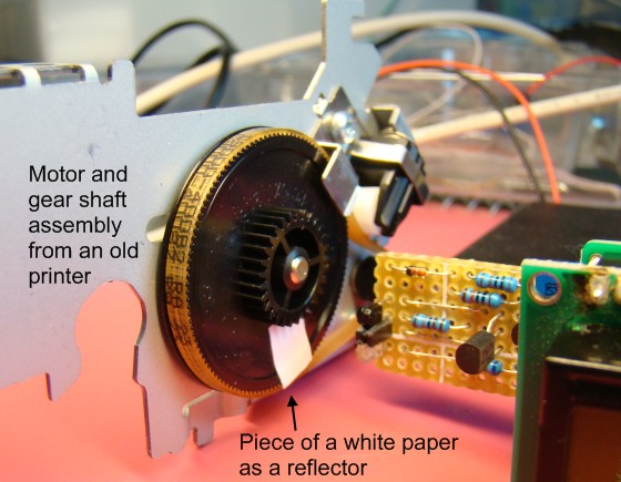
The contact with the rotating shaft is avoided with an optical sensing mechanism that uses an infrared (IR) light emitting diode and a photo detecting diode. The IR LED transmits an infrared light towards the rotating disc and the photo detecting diode receives the reflected light beam. This special arrangement of sensors is placed at about an inch away and facing towards the rotating disc. If the surface of the disc is rough and dark, the reflected IR light will be negligible. A tiny piece of white paper glued to the rotating disc is just enough to reflect the incident IR light when it passes in front of the sensor, which happens once per rotation (shown below).

Rotating disc with a reflector
If the entire disc surface is bright and reflective, use a piece of black paper instead so that the IR light will be absorbed by this portion once per rotation. In either case, a pulse will be generated at the output of the signal conditioning circuit for each complete rotation of the disc. The circuit diagram for the sensor part is shown below.

IR sensors and signal conditioning circuit
When the IR Tx pin is pulled high, the BC547 transistor (NPN) conducts and infrared light is transmitted. This is controlled through RA3 pin of PIC18F255o, and is turned on for 1 sec during which the number of reflected pulses received by the photo detecting diode are counted. The pulses appears at the collector of the BC557 transistor (PNP) goes to RA4/T0CKI pin of PIC18F2550. It is the external input pin for Timer0 module which counts the external pulses arriving at this pin. Under normal condition, the resistance of photo detecting diode is very high and therefore, the BC557 transistor is almost cut-off. The output at its collector is pulled to ground. When the photo detecting diode receives the reflected IR light, it’s resistance drops and BC557 conducts, and the collector output goes high. Thus, this simple circuit converts the reflected IR light from the white mark on the rotating disc into a pulse.
Timer0 Module in PIC18F2550
The Timer0 module in PIC16F series is 8-bit but in case of PIC18F2550, it is software selectable for 8- or 16-bit mode. Its operation is controlled by T0CON register; the function of each bit in the T0CON register is shown below.

T0CON register
For our purpose, the Timer0 module will be configured as a 16-bit counter to count the number of pulses arriving at RA4/T0CKI input pin. The counter will be active for 1 sec and the number of pulses arrived during this interval will be recorded, and later multiplied by 60 to get the RPM of the disc. Without an overflow, the Timer0 in 16-bit mode can count up to 65535, that corresponds to 3932100 RPM. However, in this project, we will limit the range up to 99960 RPM. To serve our need, we will clear T08BIT (16-bit mode) and T0SE (increment on high-to-low transition on T0CKI pin) bits, and set T0CS (counter mode) and PSA (no prescaler) bits.
Circuit setup
As I mentioned earlier, I am using StartUSB for PIC board for demonstration of this technique, and therefore, I am not providing the detail circuit diagram of this project. Rather, I will be showing the connections of LCD and the sensor unit (described above) to the board, as shown below. LCD data bits D4-D7 (11-14) are driven through RB4-RB7 pins, whereas the control pins, RS (4) and E (6) are connected to RC6 and RC7 pins of PIC18F2550. The transmission of infrared light is controlled by RA3 pin, whereas the reflected pulses are fed to the T0CKI pin. The microcontroller runs at 48.0 MHz using its internal PLL. The circuit diagram for the board itself can be found here.

LCD and sensor module connections to StartUSB for PIC board

Complete circuit setup

IR light emitting and photo-detecting diodes with a blocker in between
Software
As usual, I used my favorite mikroC compiler from mikroElektronika for programming the PIC. No external programmer is required with StartUSB board as the on-board PIC has pre-programmed with mikroElektronika’s fast USB bootloader. Those who are not familiar with StartUSB for PIC board, read my previous article Getting started with PIC18F Microcontrollers. The programming part is not very tough for this. It involves the initialization of I/O ports and Timer0 control register. The LCD interfacing part uses mikroC’s built-in LCD library functions, read my article ‘How to interface a character LCD with PIC‘ if you are new to this.
Once the program is loaded into the microcontroller, reset the StartUSB board and wait for 5 sec till it comes out of bootloader mode and starts running the application for your contact-less tachometer.

Tachometer in action
Conclusion
A digital tachometer based on an infrared light reflection technique has been demonstrated successfully. Its major advantage is that it doesn’t require any physical contact with the rotating shaft to measure its speed. This project can be extended further by adding data logging feature to it. This is required in certain applications where the RPM of a rotating shaft is needed to be monitored. The data logger will keep the records of varying RPM over time, and those records can be later transferred to a PC through the USB interface.
|
|
Sir , I want the code for the Contactless Digital Tachometer using PIC16F877A
I have used the same code and changed the port assignments according to PIC18f45k50. But the speed is not detecting properly . please help me
How can i make a simplest tachometer without using any microcontroller and making it with usage of different ICs and logic gates but it should show the speed automatically?? Kindly guide me?
I found a little mistake in code.
T0CON = 0b01101000; // TMR0 as 16-bit counter – original
T0CON = 0b00101000; //this is the correct one
From datasheet -PIC18F2455/2550/4455/4550
bit 6 T08BIT: Timer0 8-Bit/16-Bit Control bit (from datasheet)
1 = Timer0 is configured as an 8-bit timer/counter
0 = Timer0 is configured as a 16-bit timer/counter
Nice project by the way.
Hi Guys,
I’d like thank you for your info,
I’m trying to find some contact less speed detectors for production line such as pipe production line,
I’ll be thankful if provide me solution.
Nice project and i m also working on it.i want future scope and any advance technoloy for futher research.thank u.
Thank you very much for the design >>>
i just want to ask about the IR sensing circuit … it is not completely obvious.
what is the diode between 1.8k resistor and 1k resistor at RX sub-circuit.
Thank you
hi were you able to get what diode was used ?
I would like to do something similar to this. Although instead of displaying the RPM’s, I would like to keep track of time. If a tape has 60 minutes of play, I want to use this to know where exactly I am in the tape. 00:43:27 HH:MM:SS for example. Would that be possible?
I am trying to contact with you but it is not possible
so provide your contact details
I love this project , in stores in my area no PIC 18F2550 , whether it can be replaced with a PIC 18F4550 ?
Thank you
please send me the code configuration of this code for the burning of of the pic18f2550 by the use of universal code burner.
please send this as soon as possible;It’s urgent.
Sir,
Please tell me about the configuration which u are using in writing a code.
contactless tachometer is good project
hi, i am interested on this project. however i would like to make revisions but i dont know how. will it be possible to create an alarm circuit wherein if the motor stopped running, an alarm will be triggered?
thanks
I am very interested in three kits that are pre-assembled, the microsoftware is and ready to go. The emitter/sensor needs to be on cable 24″-30″ long. Otherwise I can not see the LCD screen. I need to record the day over 24 to 48 hours and have each data point be date/time tagged. I have an old laptop with both a serial port and a USB1.1 port. I will need software for the USB interface/both sides and software for the laptop record the data. It would be heaven if the laptop software included an alarm program that if RPM went above a max or below a min set by the user something would be triggered and the computer made noise. I am within reason willing to help fund development of this software if it does not exist.
Richard Bauman
BaumanRP@SWBell.net
Would it be possible to hook the sensor to a smart phone and create an app to handle the counting of pulses?
Hi I like your unit does it come as a kit, I am looking to use it in South Africa in Wet and Dirty conditions that said can the shaft sensor be changed for a magnet type sensor as the shaft get rather muddy can you let me know on bigabbs1@sky.com with price and availability
Thanks
Bri
Pingback: contact less Infra Red digital tachometer | Wiring Diagram Circuit
i need kit for doing contactless digital tachometer… pls tell me how to purchase the kit
What if i don`t use the StartUSB for pic? do i have to change the settings in MikroC PRO for Pic?
thank you!
marC:)
Sir,
It has been a great contribution from your end. The DigiTach(as I named it) works just fine and your design has been of great help to me. It was a fabulous experience working on the same and preparing its report as well. Keep me posted.
Thanks a ton again,
Sujit
Pingback: manage service provider
hi guys, i want to drive led,s direct (without limit resistor)with pic16f54…portb….can someone help me….
Pingback: Just asking for a high speed sensor..
Pingback: Contact-less Infrared Digital Tachometer | PyroElectro - News, Projects & Tutorials
Hi !
This project is very good.
But the measurement isn’t very accurate because if you have let’s say 5 and a half pulses you will get only 300 RPM instead of 330 RPM.
Regards George.
i really interested in this project. so can you give me suggestion for the data logger that i can use to combined it with this project?? how to connect this circuit to the data logger so it can store the data over time. please help me since i am doing this project for my final year project. hope you can help me since i dont have much time left to complete the project. i really appreciate if you can reply asap. thank you.
Pingback: some questions motor speed monitoring - Page 5
Hi Guys,
Great project!
I would like to use the code for a weather vane, so I was wondering if there were any pointers on how to go about converting the RPM to windspeed ?
Regards
Michael
@Michael,
I would say that information could be found from the specification of the wind sensor. They provide the characteristic transfer function to convert the frequency of pulses into wind speed. For example,
http://www.vaisala.com/Vaisala%20Documents/Brochures%20and%20Datasheets/WM30-Datasheet-B210384EN-B-LoRes.pdf
great…
Pingback: contact less Infra Red digital tachometer | How Circuits
I tried this project with 16f887. I used Timer1 and changed the LCD pins to portD instead of PortC. the results i got is not accurate!!!? when the number of pulses is more than 220 pulse per second, the results are unstable and largely changed from second to second. for values under 220pulse per second, the accuracy is good. any suggestions? dose the implementation with 18f2550 suffer from similar effect?
Anas,
How much do the readings change from second to second, can you give numbers? Try using a wider reflective portion so that you will have a longer reflective pulse. Since the RPM is high, a small timing error could give you inaccurate result. Use TMR1ON bit for enabling and disabling the timer sharply. Make sure you are clearing TMR1H and TMR1L registers before every measurement. You should use both TMR1H and L registers to obtain the true value of RPM, as TMR1L overflows after 256 counts.
I don’t have anything that fast to test my circuit.
Pingback: Electronics-Lab.com Blog » Blog Archive » How to make a contact-less digital tachometer using IR-light reflection technique
Pingback: Simple IR Bounce Tachometer | House of Mods
Pingback: Simple IR Bounce Tachometer - machine quotidienne
Nice……
It is too helpful for me….
I am trying to do something similar, and have not yet received every part. I wander if the transistor is really needed since some pins on the pic have schmidtt trigger input.
Do you know if some the pcb can be made simpler (I am very low on space for this project 🙂 )
regards,
treg.
Pingback: Simple IR Bounce Tachometer - Hack a Day