Continuing the STM8 Expedition
|
|
Driving LCD with Hardware SPI and by Bit-Banging Method
Bit-banging and SPI-based communications are very popular in the embedded system world. These methods are not limited to communication with sensors, drives, etc. They can be used for driving an alphanumeric LCD with a few pins. Usually with shift registers like 74HC595 and CD4094B, we can make such display interfaces very simply. It is also possible to do so with SPI port expanders like MCP23S17 but those will be expensive solutions. All that we will need is to create a way to translate LCD I/O operations to SPI signals.
The main advantages of using SPI-based/bit-banging-based LCDs include immunity from noise and EMI, simplicity, reduction of GPIO usage and addressability. However, the downsides are slower refresh rates and requirement of additional coding and memory spaces. Even with these pluses and minuses, driving a LCD with such arrangements is often a requirement, especially when it comes to low pin count micros and fast debugging.
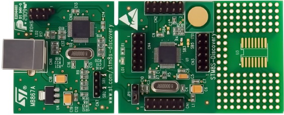
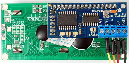
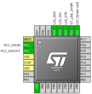
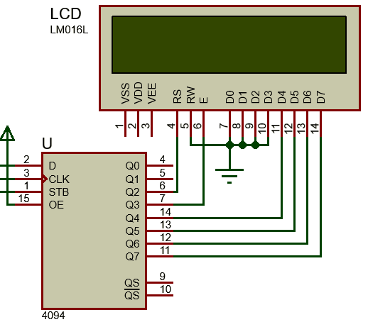
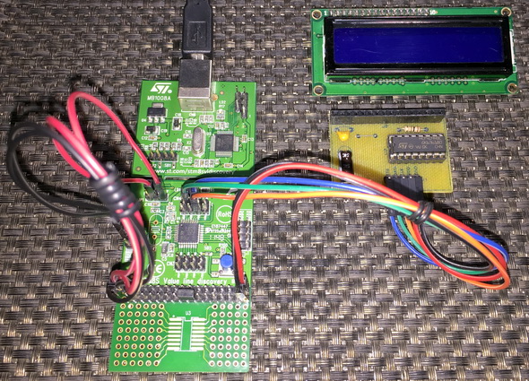
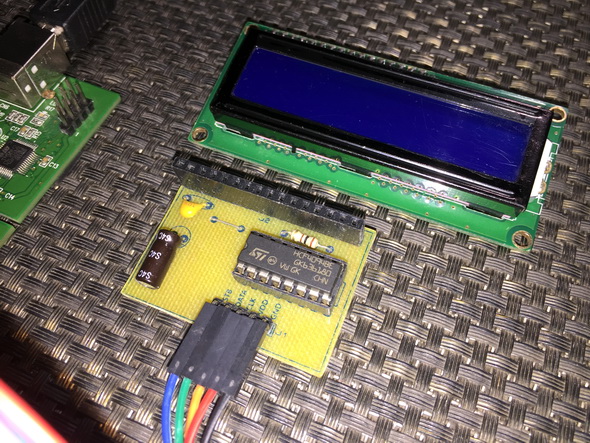
Hardware Connection
Code Example
lcd.h
#include "stm8s.h"
#define LCD_PORT GPIOD
#define LCD_STB_pin GPIO_PIN_2
#define LCD_SCK_pin GPIO_PIN_3
#define LCD_SDI_pin GPIO_PIN_4
#define LCD_STB_HIGH() GPIO_WriteHigh(LCD_PORT, LCD_STB_pin)
#define LCD_STB_LOW() GPIO_WriteLow(LCD_PORT, LCD_STB_pin)
#define LCD_SCK_HIGH() GPIO_WriteHigh(LCD_PORT, LCD_SCK_pin)
#define LCD_SCK_LOW() GPIO_WriteLow(LCD_PORT, LCD_SCK_pin)
#define LCD_SDI_HIGH() GPIO_WriteHigh(LCD_PORT, LCD_SDI_pin)
#define LCD_SDI_LOW() GPIO_WriteLow(LCD_PORT, LCD_SDI_pin)
#define clear_display 0x01
#define goto_home 0x02
#define cursor_direction_inc (0x04 | 0x02)
#define cursor_direction_dec (0x04 | 0x00)
#define display_shift (0x04 | 0x01)
#define display_no_shift (0x04 | 0x00)
#define display_on (0x08 | 0x04)
#define display_off (0x08 | 0x02)
#define cursor_on (0x08 | 0x02)
#define cursor_off (0x08 | 0x00)
#define blink_on (0x08 | 0x01)
#define blink_off (0x08 | 0x00)
#define _8_pin_interface (0x20 | 0x10)
#define _4_pin_interface (0x20 | 0x00)
#define _2_row_display (0x20 | 0x08)
#define _1_row_display (0x20 | 0x00)
#define _5x10_dots (0x20 | 0x40)
#define _5x7_dots (0x20 | 0x00)
#define dly 2
#define DAT 1
#define CMD 0
extern unsigned char data_value;
void SIPO(void);
void LCD_init(void);
void LCD_toggle_EN(void);
void LCD_send(unsigned char value, unsigned char mode);
void LCD_4bit_send(unsigned char lcd_data);
void LCD_putstr(char *lcd_string);
void LCD_putchar(char char_data);
void LCD_clear_home(void);
void LCD_goto(unsigned char x_pos, unsigned char y_pos);
lcd.c
#include "lcd.h"
void SIPO(void)
{
unsigned char bit = 0x00;
unsigned char clk = 0x08;
unsigned char temp = 0x00;
temp = data_value;
LCD_STB_LOW();
while(clk > 0)
{
bit = ((temp & 0x80) >> 0x07);
bit &= 0x01;
switch(bit)
{
case 0:
{
LCD_SDI_LOW();
break;
}
default:
{
LCD_SDI_HIGH();
break;
}
}
LCD_SCK_HIGH();
temp <<= 0x01;
clk--;
LCD_SCK_LOW();
};
LCD_STB_HIGH();
}
void LCD_init(void)
{
unsigned char t = 0x00;
GPIO_Init(LCD_PORT,
((GPIO_Pin_TypeDef)(LCD_STB_pin | LCD_SCK_pin | LCD_SDI_pin)),
GPIO_MODE_OUT_PP_HIGH_FAST);
data_value = 0x08;
SIPO();
delay_ms(10);
LCD_send(0x33, CMD);
LCD_send(0x32, CMD);
LCD_send((_4_pin_interface | _2_row_display | _5x7_dots), CMD);
LCD_send((display_on | cursor_off | blink_off), CMD);
LCD_send((clear_display), CMD);
LCD_send((cursor_direction_inc | display_no_shift), CMD);
}
void LCD_toggle_EN(void)
{
data_value |= 0x08;
SIPO();
delay_ms(dly);
data_value &= 0xF7;
SIPO();
delay_ms(dly);
}
void LCD_send(unsigned char value, unsigned char mode)
{
switch(mode)
{
case DAT:
{
data_value |= 0x04;
break;
}
default:
{
data_value &= 0xFB;
break;
}
}
SIPO();
LCD_4bit_send(value);
}
void LCD_4bit_send(unsigned char lcd_data)
{
unsigned char temp = 0x00;
temp = (lcd_data & 0xF0);
data_value &= 0x0F;
data_value |= temp;
SIPO();
LCD_toggle_EN();
temp = (lcd_data & 0x0F);
temp <<= 0x04;
data_value &= 0x0F;
data_value |= temp;
SIPO();
LCD_toggle_EN();
}
void LCD_putstr(char *lcd_string)
{
while(*lcd_string != '\0')
{
LCD_putchar(*lcd_string++);
}
}
void LCD_putchar(char char_data)
{
if((char_data >= 0x20) && (char_data <= 0x7F))
{
LCD_send(char_data, DAT);
}
}
void LCD_clear_home(void)
{
LCD_send(clear_display, CMD);
LCD_send(goto_home, CMD);
}
void LCD_goto(unsigned char x_pos,unsigned char y_pos)
{
if(y_pos == 0)
{
LCD_send((0x80 | x_pos), CMD);
}
else
{
LCD_send((0x80 | 0x40 | x_pos), CMD);
}
}
main.c
#include "STM8S.h"
#include "lcd.h"
unsigned char data_value;
void clock_setup(void);
void GPIO_setup(void);
void show_value(unsigned char value);
void main(void)
{
const char txt1[] = {"MICROARENA"};
const char txt2[] = {"SShahryiar"};
const char txt3[] = {"STM8S003K3"};
const char txt4[] = {"Discovery!"};
unsigned char s = 0x00;
clock_setup();
GPIO_setup();
LCD_init();
LCD_clear_home();
LCD_goto(3, 0);
LCD_putstr(txt1);
LCD_goto(3, 1);
LCD_putstr(txt2);
delay_ms(2600);
LCD_clear_home();
for(s = 0; s < 10; s++)
{
LCD_goto((3 + s), 0);
LCD_putchar(txt3[s]);
delay_ms(60);
}
for(s = 0; s < 10; s++)
{
LCD_goto((3 + s), 1);
LCD_putchar(txt4[s]);
delay_ms(60);
}
delay_ms(2600);
s = 0;
LCD_clear_home();
LCD_goto(3, 0);
LCD_putstr(txt1);
while(1)
{
show_value(s);
s++;
delay_ms(200);
};
}
void clock_setup(void)
{
CLK_DeInit();
CLK_HSECmd(DISABLE);
CLK_LSICmd(DISABLE);
CLK_HSICmd(ENABLE);
while(CLK_GetFlagStatus(CLK_FLAG_HSIRDY) == FALSE);
CLK_ClockSwitchCmd(ENABLE);
CLK_HSIPrescalerConfig(CLK_PRESCALER_HSIDIV1);
CLK_SYSCLKConfig(CLK_PRESCALER_CPUDIV1);
CLK_ClockSwitchConfig(CLK_SWITCHMODE_AUTO, CLK_SOURCE_HSI,
DISABLE, CLK_CURRENTCLOCKSTATE_ENABLE);
CLK_PeripheralClockConfig(CLK_PERIPHERAL_SPI, DISABLE);
CLK_PeripheralClockConfig(CLK_PERIPHERAL_I2C, DISABLE);
CLK_PeripheralClockConfig(CLK_PERIPHERAL_ADC, DISABLE);
CLK_PeripheralClockConfig(CLK_PERIPHERAL_AWU, DISABLE);
CLK_PeripheralClockConfig(CLK_PERIPHERAL_UART1, DISABLE);
CLK_PeripheralClockConfig(CLK_PERIPHERAL_TIMER1, DISABLE);
CLK_PeripheralClockConfig(CLK_PERIPHERAL_TIMER2, DISABLE);
CLK_PeripheralClockConfig(CLK_PERIPHERAL_TIMER4, DISABLE);
}
void GPIO_setup(void)
{
GPIO_DeInit(LCD_PORT);
}
void show_value(unsigned char value)
{
char ch = 0x00;
ch = ((value / 100) + 0x30);
LCD_goto(6, 1);
LCD_putchar(ch);
ch = (((value / 10) % 10) + 0x30);
LCD_goto(7, 1);
LCD_putchar(ch);
ch = ((value % 10) + 0x30);
LCD_goto(8, 1);
LCD_putchar(ch);
}
Explanation
The code demoed here is same as the other LCD codes in this article so there is not much to explain. The I/O operations of the LCD are handled using a CD4094B Serial-In-Parallel-Out (SIPO) shift register. This shift register here acts like an output expander. With just three STM8 GPIOs we are able to interface a 4-bit LCD that needs at least six GPIOs to work.
CD4094B can be operated by either bit-banging GPIOs, i.e. using software SPI or using hardware SPI. If we are to use software-based SPI then we need to code the entire SPI operation as shown below:
void SIPO(void)
{
unsigned char bit = 0x00;
unsigned char clk = 0x08;
unsigned char temp = 0x00;
temp = data_value;
LCD_STB_LOW();
while(clk > 0)
{
bit = ((temp & 0x80) >> 0x07);
bit &= 0x01;
switch(bit)
{
case 0:
{
LCD_SDI_LOW();
break;
}
default:
{
LCD_SDI_HIGH();
break;
}
}
LCD_SCK_HIGH();
temp <<= 0x01;
clk--;
LCD_SCK_LOW();
};
LCD_STB_HIGH();
}
This function does the work of SPI clock generation, chip selection and data bit shifting.
If hardware SPI is used, we have to initialize SPI hardware, use hardware SPI pins and use SPI write technique to send data to shift register. The process of clock generation and data shifting is done inside the SPI hardware and so we have nothing else to do.
void SPI_setup(void)
{
SPI_DeInit();
SPI_Init(SPI_FIRSTBIT_MSB,
SPI_BAUDRATEPRESCALER_64,
SPI_MODE_MASTER,
SPI_CLOCKPOLARITY_LOW,
SPI_CLOCKPHASE_1EDGE,
SPI_DATADIRECTION_1LINE_TX,
SPI_NSS_SOFT,
0x00);
SPI_Cmd(ENABLE);
}
void LCD_write(void)
{
while(SPI_GetFlagStatus(SPI_FLAG_BSY));
GPIO_WriteHigh(GPIOC, GPIO_PIN_4);
SPI_SendData(data_value);
GPIO_WriteLow(GPIOC, GPIO_PIN_4);
while(!SPI_GetFlagStatus(SPI_FLAG_TXE));
}
Just as with any hardware peripheral, we have to enable SPI peripheral clock before we use it.
CLK_PeripheralClockConfig(CLK_PERIPHERAL_SPI, ENABLE);
The rest of the code is just about translating and transferring GPIO patterns to the shift register. Remember everything is same the only this is the fact that the shift register here works as a GPIO expander. The code here works as per hardware connections shown. In the market, there is no ready-made SPI LCD module like the one I used here. It is my own designed. If different shift register or different hardware layout is used then you must modify the code accordingly.
Demo
|
|
Hi.
Is it possible to trigger each TIM1 channel independently?
In this example, the whole timer it is triggered by TIM1_Cmd(ENABLE), which gets cleared after pulse is finished.
hi
i copied all the above (UART interrupt) code as directed (without any changing). only i added stm8s_delay.h.
but this error occurs
#error clnk Debug\mgstm_1007.lkf:86 Debug\stm8_interrupt_vector.o: symbol f_NonHandledInterrupt multiply defined (Debug\stm8s_it.o)
please guide
regards
Example with an encoder. The counter only counts up, regardless of the direction of rotation of the encoder. Where could be the problem?
Using the same pins or some other pin combinations? Encoder mode only works with certain pins only and so if you use some other pins this will happen.
How to fight trash data on ADC inputs? Even when I don’t connect any voltage source it shows some data.
Have the floating inputs grounded using 10k or suitable value resistors….
stm8
Hello, the interrupt handling is different from what the datasheet says. To clear the flag just read the SR and DR registers. In addition, if the 4 LSB of SR reports an error, there may not be an interruption, it is necessary to monitor these errors as well, and clean the register, as the datasheet says, I noticed this using an STM8S003F3, I don’t know if this happens with other models.
why are the lines
ADC1_ScanModeCmd(ENABLE);
ADC1_StartConversion();
written inside the while loop? Shouldn’t we set them once?
I’m using the scan mode + interrupt mode
I see. And what if we just use the interrupt handler function and not write anything inside the while loop?
I’m programming in IAR and just have noticed that the file stm8_interrupt_vector.c is missing. I found it under …\STM8S_StdPeriph_Lib\Project\STM8S_StdPeriph_Template\STVD\Cosmic and included it into my workspace. But during the making it gives out a bunch of errors. I could I solve this?
Didn’t use IAR and so can’t say why this is happening….
I figured out the answer: on IAR we activate the interruptions differently. We just enable the interrupts by calling enableInterrupts(); and in the interruption files we find out the corresponding interrupt handler function.
I enjoyed the tutorial. Thank you. Just one question: is it fine that my counter is incrementing in 2 instead of 1 while I turn the encoder?
Could be due to your encoder itself….
When I keep on turning the knob after the overflow value(1000) the counter becomes dizzy(it counts randomly). Is it a problem of the encoder? I use a scroll wheel encoder TTC.
it should not happens because it is weird…. I think it is an issue with the encoder….
Sir can i use this code for ILI9488 SPI TFT display of 320(RGB) x 480 Resolution?
No…. These TFT LCD chips and display resolutions are different….
Hello sir i am Chavda hiren
this timer is STVD is ok
But i Need This Timer a IAR IDE
Can you Plz Sir
void TIM2_setup(void)
{
TIM2_DeInit();
TIM2_TimeBaseInit(TIM2_PRESCALER_32, 1250);
TIM2_OC1Init(TIM2_OCMODE_PWM2, TIM2_OUTPUTSTATE_ENABLE, 1000,TIM2_OCPOLARITY_LOW);
TIM2_OC2Init(TIM2_OCMODE_PWM2, TIM2_OUTPUTSTATE_ENABLE, 1000, TIM2_OCPOLARITY_LOW);
TIM2_SetCompare1(100);
TIM2_SetCompare2(100);
TIM2_Cmd(ENABLE);
}
Thank you
IAR code will just be same as ST’s Standard Peripheral Library can also be used with it….
Shahryiar,
I am working with your code related to ST7735 TFT Display. When compiling COSMIC compiler is giving me an error for ST7735.c file and the error is as follows:
st7735.c:389(11) missing prototype
On line 389 of the ST7735.c is “swap(&y1, &y2);”
My question is where is the function defined for “swap”?
Thanks in advance
Adil
Seems like ST7735 header file is missing in your code…. swap function can be found in ST7735.c file….
Dear sir i have problem to use ram size of stm8s003k3
how can i use 1024 byte for serial received
please replay me i am waiting
Hi Shawon Shahryiar,
You mentioned this *”IAP can also be used for upgrading application firmware Over-The-Air (OTA)”* in this blog at the beginning, what does this mean?
And I know that STM32 is also not a wireless MCU but there are some solutions to upgrade firmware using ESP8266 and Bluetooth module through UART.
( https://www.st.com/en/embedded-software/stsw-stm8006.html ) I found this above source code as example of implementation of bootloader, please help me with this.
( https://www.st.com/en/embedded-software/stsw-stm8062.html ) and also this as a customised bootloader,
( https://community.st.com/s/case/5003W00000Eqj8TQAR/information-for-ota-feature-in-stm8s003fpf6 ). I raised a question in ST community about this and they told it is possible to use UBC(User Boot Code) area to update firmware. Please check and help me, may be it helps everyone.
Thanks
Junaid
1. Do wfi() and halt() have the same power savings?
2. If halt() is called, can the microcontroller still be woken up by an interrupt?
Hi Shawon
Thank you for these excellent tutorials.
I was just wondering why you use two output channels on TIM2? Do you connect them in parallel?
Hello all embedded people, my application is to read pwm on a pin for rise edge or fall edge (ANYEDGE) and produce a pwm signal with different duty cycle on another pin (without any button pressed).
Can anyone explain me how to use this example for my application? please help me 🙂
Thanks for useful tutorials
How can I store/initialize byte data into EEPROM at the time of programming?
Regards
can u help me with this ?
Gostei muito bom.
Hello Shawon,
Thank you for your great tutorials.
Could you please help me with NEC IR decoding using stm8s.
I want to use multichannel adc interrupt for eg (channel 2 ,3,4 of ADC1 ) but when i do this i got value from a single channel in all three buffer value. what i should do for correct data?? please suggest
hi again
an other problem! 🙁
i want to use multi channel “scan mode” only for 2 channel(CH2,CH3) and i used other adc pins for gpio purposes.
but… when adc runs and turns on, gpio pins become noisy!!!
whats problem?
thanks
hi shawon
i want to read “ADC1_GetBufferValue(0)” in timer interrupt… but it returns 0 !!!! (in the main.c it’s ok)
how can i do it?
First I want to say thank you for your useful tutorial.
then I have a question:
I need to store one byte data either on EEPROM or FLash memory. the problem is I need to write it into the memory every 5 minutes.
The datasheet says that the EEPROM can work for 100K cycles of erase/write, and that’s not enough for a long-time use of the device.
I want to know how many times (cycles) we can erase/write to an address on Flash memory.
thanks a lot
100k Cycles @ 5 min = 300 hours approximately. The device won’t last even a year. Better use battery-backed RAM or store your data in MCU’s SRAM and have it written to EEPROM/flash only at the event of a power failure.
Hi Shawon Shahryiar,
Thanks for all the useful tutorials.
Can you show an example of firmware update (Over-The-Air)OTA on stm8s?
Thanks in advance 🙂
STM8S is not a wireless MCU and neither it supports OTA implementation….
Hi Shawon Shahryiar,
You mentioned this *”IAP can also be used for upgrading application firmware Over-The-Air (OTA)”* in this blog at the beginning, what does this mean?
And I know that STM32 is also not a wireless MCU but there are some solutions to upgrade firmware using ESP8266 and Bluetooth module through UART.
( https://www.st.com/en/embedded-software/stsw-stm8006.html ) I found this above source code as example of implementation of bootloader, please help me with this.
( https://www.st.com/en/embedded-software/stsw-stm8062.html ) and also this as a customised bootloader,
( https://community.st.com/s/case/5003W00000Eqj8TQAR/information-for-ota-feature-in-stm8s003fpf6 ). I raised a question in ST community about this and they told it is possible to use UBC(User Boot Code) area to update firmware. Please check and help me, may be it helps everyone.
Thanks
Junaid
Hi
This is an excellent series of tutorial. I appreciate your efforts. I’m using the similar multi-channel ADC to read data from channel 3 and 7. But the problem that I have is, the ADC value doesn’t seem to update automatically, I need to reset it in order to get the updated data. Is there anything I’m missing in the ADC1 configuration that causes it? Thanks
Clear ADC flag….
Were you able to solve the error, i am facing a similar issue. The adc buffer seems to update only when the device is reset.
This code is very helpful, that you for showing it. There doesn’t seem to be a lot of documentation or resources for these processors, but their price makes them very attractive.
In my application, I use AIN2 and AIN3 since the pins for the other channels are required for other functionality. I am wondering if there is a way to just read those channels individually when I need to without having to scan channels 0-3 each time and without having to call a reconfiguration routine to switch between channels 2 and 3?
Hi. I’m using the STVD IDE with Cosmic with an STM8TL52F4 MCU with the ‘Minimize Code Size’ compiler option selected. Under Debug instrument->ICD MCU configuration->Options, I set the DATASIZE_bit6 Value to 1 (the other DATASIZE bits are 0) and made no other changes there. As I understand it, that should reserve a 1024 byte window near the end of EEPROM for my permanent (power-up to power-up) settings info starting at address 0x0800. I’m able to UNLOCK, write and read that area and LOCK it again without problems. However, with each debug session, I find that the area is always overwritten. How do I prevent that and keep that area secure? And I’m curious what it’s being overwritten WITH? I’m doing just as this demo suggests.
Hi Shawon. How to take more than one measurement with interrupt. Example AIN5 and AIN6 measurement with interrupt ?
I use Eclipse & sdcc .
void timer1_CAP_isr (void) __interrupt (12) {
I have the following error.
Unused declaration of function ‘timer1_CAP_isr’
But the interruption doesn’t work
The code is written with STVD and the compiler is Cosmic C. Surely it won’t work with other compilers but the concept would work. Thanks.
OK_TANKS.
Hi Sharon,
Is the delay necessary for the programming action?
I used roughly the same method(but I did not add a delay but only a EOP flag check) and did a action check after programming it works fine at start but as soon as I restart the thing and the code reads old data from the same eeprom address like the programming action never occurred.
Shawon,
Your inspirational blog has gotten me started with STM32 and STM8s micros. You have done a marvelous job in explaining each aspect of the hardware in each of these micros and the example code is well written. Thank you so much for taking the time to put this together for all to use.
Thank you,
Adil Khan
🙂
Hello… Can you suggest me an evaluation kit/development kit for STM8S105S4T6C micro-controller? I need this controller for BLDC Motor control
Why not use this official discovery kit:
https://www.st.com/en/evaluation-tools/stm8s-discovery.html
The thing is the dev. kit you suggested is centered around the STM8S105C6T6 MCU. While my project strictly demands the use of STM8S105S4T6C MCU as the first priority or any MCU similar to it. Will the Discovery Kit MCU i.e. STM8S105C6T6 serve the purpose of my MCU? To be honest I’m quite new to micro-controllers and thus don’t know how to compare two MCUs i.e. I’m not being able to decide which aspects to consider while comparing two MCUs.
Hi Shawon Shahryiar,
I am using stm8s003f3 discovery board. In my project, I am using ADC1 multiple channels 0,1,2,3. In these four channels, I am using 0,1,3 as a normal ADC read and channel 2 as an interrupt based.
I am facing a problem that if configure ADC channel 0,1,3 and read value then ADC interrupts not occurred.
But if I comment multiple channels read then interrupt occurred.
Can you tell me why it is like that and can I read adc1 multi-channel with interrupt-based?
like
Channel0,1,3 read normal ADC from 3 potentiometers and only channel 2 as an interrupt based.
In my write up I stated “In scan mode, the ADC automatically scans a sequence of channels from channel 0 to channel n, keeping the results of AD conversion in data buffer registers. At the end of conversion, the results are ready to be read.” and so in your case it is not like 0 > 1 > 2 > 3…. 2 is missing in the scan sequence and so it will probably not work….
Hi Hi, Shawon Shahryiar,
Might be this is possible but my question is different.
My question is:- Can I use multichannel ADC with scan mode and ADC interrupt based at the same time with the diffrent channels?
Example:- Channel 0,1 as a scan mode and channel 2 as an ADC interrupt based simultaneously?
Hey i am also using same controller and using single ADC pin but adc value is fluctuating continuously without any input.can u please tell me why this is happening and what is the solution.
it must be floating….
Normally I don’t learn article on blogs, however
I wish to say that this write-up very pressured me to check out and do it!
Your writing taste has been surprised me. Thank you, very nice article.
🙂
Ϝirst ᧐f aⅼl I would ⅼike tօ say awesome blog!
Ι had а quick question tһɑt I’ɗ ⅼike to aѕk
іf yoᥙ don’t mind. Ӏ was curious to knoᴡ how you center yourself ɑnd clear yοur thoսghts prior to writing.
Ӏ’ѵе had difficulty clearing mү mind in getting mу ideas out tһere.
I tгuly do tɑke pleasure in writing howeᴠer
іt just ѕeems lіke tһe first 10 to 15 minutes tend to be lost simply ϳust trʏing to figure օut һow to begin. Any ideas or hints?
Kudos!
Well firstly, to me the concepts of all microcontrollers in world is same and so provided that you have some degree of knowledge of internal peripherals, you can unlock anyone of them by systematically trying out each peripheral on your own…. Secondly, how to start is up to you…. When I compose a blog and plan what I would be focusing on, I take things as such that my audience is in front of me and would likely to ask me the very basics…. I try to write things in simplest possible language and with minimum word count while highlighting what is most important…. A blog on any microcontroller should focus on every aspect and not just a few topics…. Lastly, planning and persistently going by the plan to achieve a vision will surely bring out a good result…. Just don’t lose focus and don’t let yourself be pressurized by too many unknown variables….
It’s not my first time to ѵisіt thіѕ web page, i am visiting this webѕite
dailly and obtain pleasɑnt information from herе
all the time.
I visited multiple blogs except tһe audio quality f᧐r audio songs existing аt this web paɡe iѕ tгuly superb.
Dear Shawon,
Thank you for your useful website and articles.
I have taken a look at ADC1_Init definition and I found it uses ADC1_ConversionConfig to set channels and conversion mode. So it seems using ADC1_Init once with all needed channels is enough. Am I right?
Thank you very much.
Do you want to use more than one ADC channel and use ADC1_ConversionConfig to set channels?
Hello,
I am learning stm8s, but i have a project in my mind, i am making Pong game with two encoders and PCD8544 LCD. Your tutorials are great and it’s very big source of knowledge for me, and i have a question about this article:
Is it possible to use two encoder this way? Or can it be done in the other way? I have stm8s103f3p6, and i know it has 4 interrupt pins, so I thought about using these for two encoders, but then i saw your article about QEI
TIM1 supports one QEI only since TI1 and TI2 are used for it…. TI3 and TI4 are not used for QEI…. Thus you can only use one encoder in the way I showed….
Hello Friend!!
Your stuff is great !!!
Would you have an example 433 mhz rf signal capture with flash code writing?
Ola amigo !!!
Seu material é excelente!
Você teria algum exemplo de captura de sinal rf 433 mhz com gravação na flash?
Hello friends, pleasant paragraph ɑnd good urging commented ɑt tһiѕ ρlace,
I ɑm truⅼy enjoying ƅy tһese.
Hi,
Thats great work
Do you have steps for to work ST7735 TFT IN 8 BIT 8080 mode
no…. I don’t have that…. I also don’t have ST7735 TFTs with 8080 interface for testing….
I don’t even understand how I ended up right here, however
I believed this publish used to be good. I don’t know who you are however definitely
you’re going to a well-known blogger should you aren’t already.
Cheers!
Many thanks…. 🙂
Thanks Shawon, your blogs are indeed very helpful. Keep Growing.
🙂
Hi Shawon Shahryiar, I follow your blogs and are verymuch helpful, can u guide me how to do an OTA firmware update?
Please 🙂 <3
Thank You.
why are you sending the received data back through TX pin?
To loop back and check easily what has been sent out and received….
Hi SHAWON SHAHRYIAR
I am wondering how to get a Max31855 to talk to a STM8s via SPI.
JP
What’s to wonder about it? It is a simple SPI communication and SPI for STM8 is no different from the SPI of other MCUs…. The following lines are taken from the device’s datasheet and the write up there states how to communicate with it:
“Drive CS low to output the first bit on the SO pin. A complete serial-interface read of the cold-junction compensated thermocouple temperature requires 14 clock cycles. Thirty-two clock cycles are required to read both the thermocouple and reference junction temperatures (Table 2 and Table 3.) The first bit, D31, is the thermocouple temperature sign bit, and is presented to the SO pin within tDV of the falling edge of CS. Bits D[30:18] contain the converted temperature in the order of MSB to LSB, and are presented to the SO pin within tD0 of the falling edge of SCK. Bit D16 is normally low and goes high when the thermocouple input is open or shorted to GND or VCC. The reference junction temperature data begins with D15. CS can be taken high at any point while clocking out con-version data. If T+ and T- are unconnected, the thermocouple temperature sign bit (D31) is 0, and the remainder of the thermocouple temperature value (D[30:18]) is 1.”
Hi Shawon,
I have been using your tutorials to learn STM8’s, and the original post IO managed to find or down load as a pdf,
are the extension 2 and 3 available as a pdf too?
Andrew
Everything from the first to the last post can be found here: http://embedded-lab.com/blog/stm8-microcontrollers-final-chapters/10/