Getting acquainted with the chipKIT programming tool
|
|
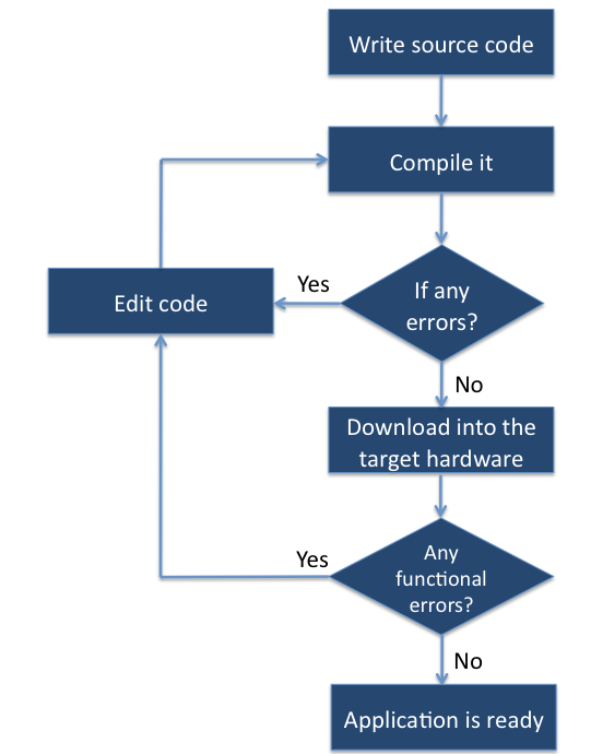
The overall process of designing a microcontroller-based system is divided into two parts: designing the hardware of the system, and writing the control software for it. Before the design cycle begins, it is important to have good knowledge of the tools available for the chosen development platform. While we already explored the hardware features of the chipKIT UNO32 board in Exploring the chipKIT Uno32 board, it’s time to look at the software development process. The flowchart below gives an overview of how an application program is developed for the chipKIT board.

Software development process for the chipKIT board
Application programs for chipKIT boards are developed using a modified version of the original Arduino programming tool. It is called Multi-Platform Integrated Development Environment (MPIDE), and it works for chipKIT and most of the Arduino development boards. The programs written for Arduino are usually called Arduino Sketches. Since chipKIT is an Arduino-style platform, chipKIT programs will henceforth be referred as chipKIT sketches or just sketches.
In order to write your chipKIT sketches, you should have MPIDE installed on your PC. You can download MPIDE from this link: https://github.com/chipKIT32/chipKIT32-MAX/downloads
MPIDE runs on MAC OS, Windows, and Linux machines. While downloading MPIDE, select the right package for your operating system. The installation process is straight forward. Unzip the downloaded package, and the executable program is ready to use. You can place the unzipped folder anywhere in your computer. Please refer the instructions available on MPIDE wiki page if you have any issues with the installation.
A brief tour of the MPIDE tool
When you open the MPIDE program in Windows operating system, it will look something like shown in the picture below. If you are using Linux or MAC OS, you may see some differences in the look of the IDE, but functionally they are all same.

MPIDE program window
In the MPIDE, you will see a blank white space to write a sketch and a blue color toolbar across the top that contains seven shortcut buttons to provide quick access to the most commonly used functions within the IDE.

MPIDE toolbar
The table below briefly describes the functions of each button in the toolbar.
| Verify | Checks your code for any errors |
| Upload | Uploads the current sketch to the chipKIT board’s program memory |
| New | Creates a blank editor window for a new sketch |
| Open | Opens an existing chipKIT sketch |
| Save | Saves the current sketch file |
| Serial Monitor | Opens a serial monitor terminal that displays data being sent by the chipKIT board through serial port. It also allows you to send serial data back to the chipKIT board. |
There is a message area at the bottom of the MPIDE window. If there are any errors while connecting to the chipKIT board, verifying code, or uploading code, they will be displayed here in red text.
Configuring the MPIDE for chipKIT UNO32
Connect your chipKIT UNO32 board to your computer using the USB cable. Then open the MPIDE and select Tools->Board from the drop-down menu and select chipKIT UNO32 from the list. Next, go to select Tools-> Serial Port, which will give you the list of available serial ports on your computer. In Windows machines, serial ports are listed as COM1, COM2, COM3, …. Select the right COM port number for your chipKIT UNO32 board. You can figure out which serial port is assigned to your chipKIT UNO32 by visiting the control panel in Windows.

Select chipKIT UNO32 from Tools->Board

Select the right COM port number for your chipKIT board
Writing a chipKIT sketch
We had a the brief tour of the MPIDE tool and now it’s time to write a test sketch for the chipKIT UNO32 board. There are two user LEDs on the board. They are labeled as LD4 and LD5 on the board and are connected to digital I/O pins 13 and 43, respectively. We will write a demo program to flash these LEDs alternately with a duration of 500 milliseconds. The board will get power supply from the USB port. This simple program will make sure that the chipkit UNO32 board is working and the MPIDE tool is installed and configured properly. Since the test LEDs are already on the board, you need nothing else than the chipKIT UNO32 board and an USB cable to perform this experiment.

User LEDs on the board
Open the MPIDE programming tool and click on New Sketch button on the toolbar. You will see an empty sketch editor. If you didn’t assign a name, the MPIDE will give a default name to the new sketch starting with sketch_. You can change the name anytime you want by using the File->Save As command. You can save the sketch to wherever you like and the MPIDE will automatically create a folder for each project with the same name as of the sketch. Now type in the following code into the blank sketch editor window. This chipKIT sketch will make the two on-board user LEDs to flash alternately.
/*
  Tutorial 1: Flashing LEDs
  Description: Two on-board LEDs connected to digital I/O pins 13 and 43
               will blink alternately with a duration of 500ms.
  Board: chipKIT UNO32
 */

void setup() {
  // Initialize the digital pins 13 and 43 as output.
  pinMode(13, OUTPUT);
  pinMode(43, OUTPUT);
}

void loop() {
  digitalWrite(13, HIGH);   // set pin 13 high
  digitalWrite(43, LOW);    // set pin 43 low
  delay(500);               // wait for 0.5 second
  digitalWrite(13, LOW);    // set pin 13 low
  digitalWrite(43, HIGH);   // set pin 43 high
  delay(500);               // wait for 0.5 second
}
Description of the sketch
All chipKIT sketches must have at least two functions: setup() and loop(). The setup() is the first function to run in the program when the chipKIT board is first powered on or the reset button is pressed. The instructions written inside the setup() function are executed only once. This function is mostly used to configure the chipKIT I/O pins and other peripherals. On the other hand, the loop() function contains the actual core program, and is executed repeatedly for ever. Both of these functions must be included in a sketch even if there are no statements to run.
Any line starting with // is ignored by MPIDE. These lines are used to write comments in the code. Well-written comments help us to recall the logic we implemented in the code when we first wrote it. It also helps other people to understand the code. If there are multiple lines of comments in sequence you can avoid multiple occurrence of // at the beginning of each line by putting the entire comment block between /* and */. Anything inside /* and */ will be ignored by the MPIDE.
The first 6 lines in the above sketch makes a comment block and is ignored by the MPIDE. It just describes what the sketch is about and is helpful for readers to understand what we are trying to do. Next starts the setup() function, inside which are two pinMode instructions. The pinMode instruction is used to configure a pin type. For instance, pinMode(5, INPUT) will set the digital I/O pin 5 as an input pin. In this case, pins 13 and 43 are set as output pins as they are going to drive LEDs.
Then follows the loop() function which contains the actual operational code. The digitalWrite instruction sets the specified pin to logic HIGH or LOW. For example, the digitalWrite(13, HIGH) instruction sets the digital I/O pin 13 to logic HIGH, which means the output voltage at this pin is about 3.3 V, and the LD4 LED is turned on. Similarly, digitalWrite(43, LOW) pulls the output pin 43 to ground.
The delay instruction makes the processor to wait for a specified amount of time (milliseconds) before executing the next instruction. For example, delay(500) makes the processor to pause for 500 milliseconds which is equivalent to 0.5 seconds.
Since the loop function repeats continuously, the LEDs will flash for ever, until the power supply is disconnected.
Compiling and downloading
Once you finish typing in the above source code, save the sketch to your desired location. Then click on the Verify button in the toolbar. The MPIDE will compile the program and check for any syntax errors. If there are any errors, you will be able to see them in the message area at the bottom. Otherwise, if the compilation was successful then the MPIDE displays only the total size of the program (bytes) in the message window.
After the successful compilation, the sketch is ready to be downloaded into the flash program memory of the PIC32 processor on the Uno32 board. Make sure that the board is connected to the PC through the USB cable and the MPIDE is properly configured for chipKIT Uno32, following the procedures described earlier. Click on the Upload button in the toolbar to download the sketch into the Uno32 board. During the download process, LED1 and LED2 are seen blinking that indicates that the communication between the MPIDE and the chipKIT Uno32 board is going on. When the upload is complete, the chipKIT Uno32 board will be reset automatically and starts executing the user application that has been just downloaded into its program memory. You will see the two user LEDs flashing alternately with a 500 ms duration.

LEDs flashing alternately
Summary
Applications for chipKIT development boards are developed using MPIDE, which is a modified version of the popular Arduino IDE. The MPIDE runs on Windows, MAC and Linux machines. This tutorial provided a brief overview of MPIDE, its installation and configuration for chipKIT Uno32 board. The overall application development process with MPIDE was illustrated with a very basic example sketch of flashing the two user LEDs on the chipKIT Uno32 board.
Go to the main tutorial page : chipKIT Programming and Interfacing
Go to the next tutorial page : Digital input and output
|
|