chipKIT Programming and Interfacing
chipKIT is an open source embedded development environment based on the Arduino concept. The major difference between the two platforms is the type of processor used in their hardware. The Arduino development boards are based on 8-bit Atmel microcontrollers which run at maximum clock speed of 16 MHz . On the other hand, the chipKIT hardware uses powerful 32-bit PIC processors running at 80 MHz clock, and thus provides improved performance over the traditional Arduino boards. Every effort has been made by the designers of chipKIT to make it compatible with Arduino so that most of the existing Arduino shields and software libraries can also be used with the chipKIT boards. The objective of the following tutorials is to provide a comprehensive introduction to the chipKIT platform and ensure that any beginner, student or hobbyist, will quickly be able to start using it for their own embedded projects and designs.
Inspired from the growing influence of Arduino, Microchip and Digilent, in 2011, introduced a new and much powerful form of Arduino platform, called chipKIT, which is based on 32-bit PIC processors. The chipKIT platform consists of two development boards (
chipKIT UNO32 and
chipKIT MAX32), and an open-source software development tool, which is basically a modified version of the Arduino IDE.
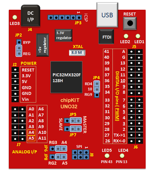
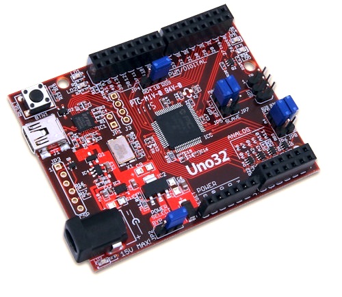
The chipKIT Uno32 development board is based on the powerful PIC32MX320F128 microcontroller, which features a 32-bit MIPS processor core running at 80MHz, 128K of flash program memory, and 16K of SRAM data memory. The board can be powered via USB or an external power supply. The on-board USB-UART interface provides a communication path between the board and the MPIDE tool running on the PC.
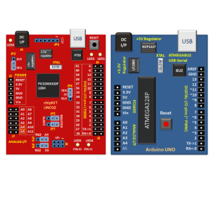
The chipKIT Uno32 is the same form factor as the Arduino Uno board and, therefore, is physically compatible with Arduino Uno shields. However, the two boards are based on completely different processors and that results in some hardware incompatibilities between the two. In order to make sure that a particular Arduino shield would work with the chipKIT Uno32, it is very important to understand these incompatibilities.
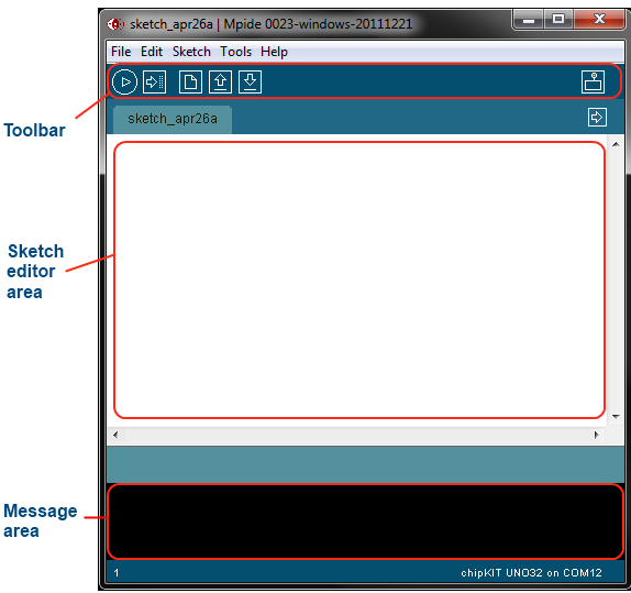
Application programs for chipKIT boards are developed using a modified version of the original Arduino programming tool. It is called Multi-Platform Integrated Development Environment(MPIDE), and it works for chipKIT and most of the Arduino development boards. In order to write your chipKIT sketches, you should have MPIDE installed on your PC.
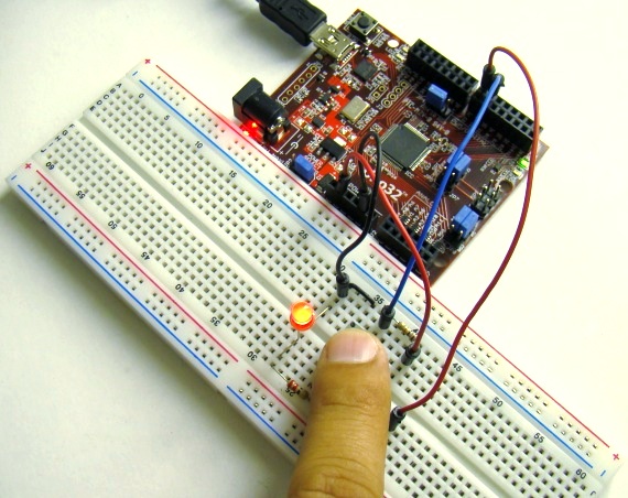
Our first tutorial is about reading and writing digital data from and to an I/O pin of the chipKIT board. Digital inputs are useful to determine whether an incoming digital signal is logic HIGH or logic LOW. A simple application is reading an input from a tact switch and perform some action based on if the switch has been pressed or not.
The chipKIT Uno32 development board is based on the powerful PIC32MX320F128 microcontroller, which features a 32-bit MIPS processor core running at 80MHz, 128K of flash program memory, and 16K of SRAM data memory. The board can be powered via USB or an external power supply. The on-board USB-UART interface provides a communication path between the board and the MPIDE tool running on the PC.
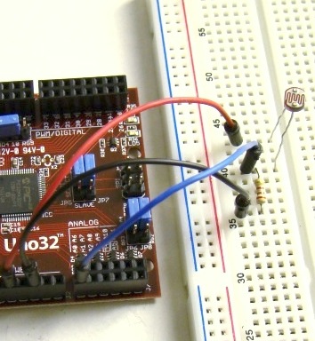
We live in an analog world where most physical variables are analog signals. However, a microcontroller can only process data that is available in digital format. It is precisely for this reason that the analog-to-digital conversion (ADC) is so important in any embedded system that interacts with an analog environment. In this tutorial, we will discuss about the ADC capabilities of chipKIT UNO32 board.
LCD displays can add a lot to your application in terms of providing an interactive user-interface, and debugging an application. The most common type of character LCD controller is the Hitachi 44780, which provides a relatively simple interface between a processor and an LCD. This tutorial describes how to interface Hitachi 44780 based LCDs to chipKIT.
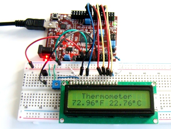
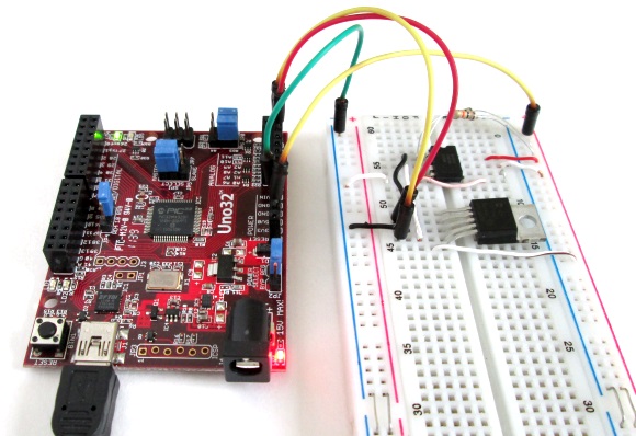
Making a digital thermometer is a good choice of project for now as it provides an opportunity to practically implement the knowledge we have gained so far from the first four tutorials. This project uses the LM34 sensor for measuring the room temperature. The sensor’s analog output is read by the chipKIT Uno32 and the temperature is displayed on LCD, in both degree Celsius and Fahrenheit scales.
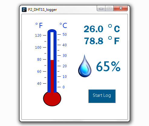
This project is about building a PC-based temperature and relative humidity logger using the chipKIT Uno32 board and the DHT11 sensor. The Uno32 reads the temperature and relative humidity from the DHT11 sensor at preset interval and sends the data to PC through the USB-UART interface. A PC application is developed using the open-source Processing programming platform to log data onto an ASCII file.
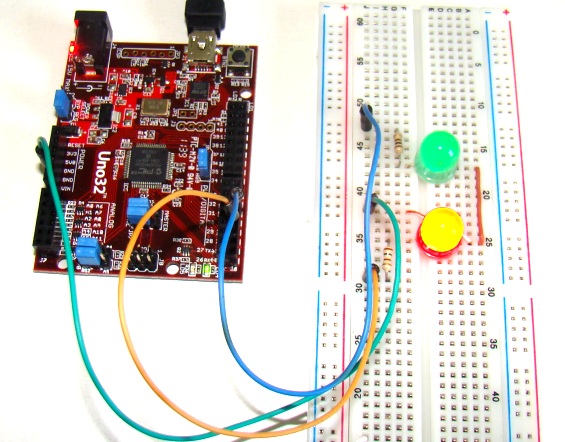
Pulse width modulation (PWM) is a technique of controlling the amount of power delivered to an electronic load using an on-off digital signal. This method is commonly used for controlling speeds of DC motors and brightness of lamps. In this tutorial, we will discuss about the PWM pins of the chipKIT Uno32 board and illustrate the concept by controlling the brightness of two external LEDs.
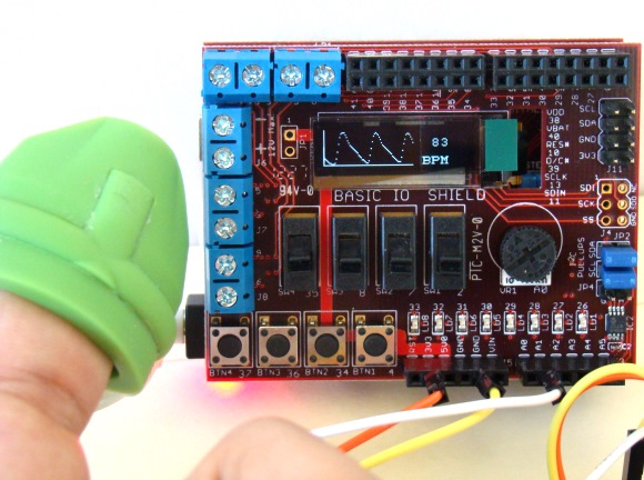
This is a third project in our chipKIT tutorial series and today we are going to construct a simple pulse rate meter using our Easy Pulse sensor with Digilent’s chipKIT Uno32 board. Digilent’s chipKIT Basic I/O shield is also used in this project for displaying the pulse waveform and the pulse rate.
In this tutorial, we will explore the chipKIT Wire Library for establishing an I2C communication link between the chipKIT Uno32 board and two I2C sensors. The Uno32 board receives the sensor outputs through the I2C link and displays the results on the serial monitor window on the computer screen.
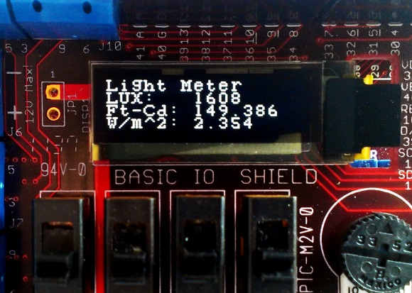
This project describes making of a digital light meter using the chipKIT Uno32 board and the BH1750 digital light sensor. The measured light intensity is displayed on an OLED screen (from the chipKIT I/O shield) in Lux, foot-candles, and Watts/m^2.
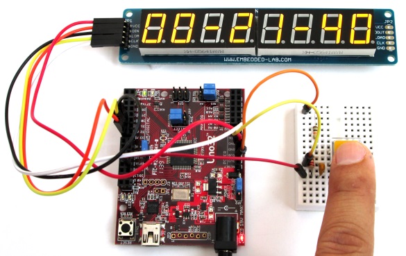
In this project, we build a digital stopwatch capable of timing minutes, seconds, and 1/10th of seconds, and with a basic start and stop control feature. A MAX7219-driven 8-digit seven segment LED display is used with chipKIT Uno32 board to display the time elapsed.
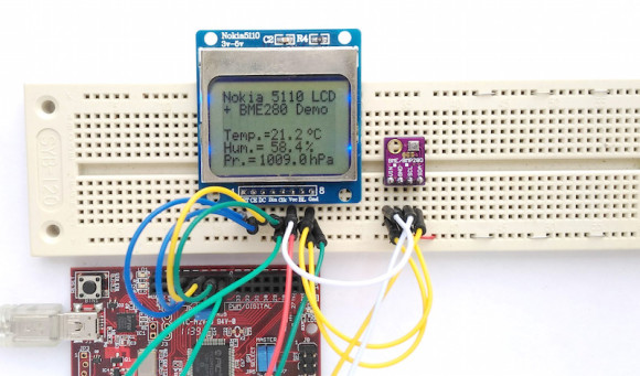
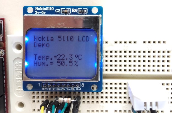
In Tutorial 4, we learnt interfacing an HD44780-based LCD to a chipKIT board for displaying alphanumeric output. Today, we will see how to connect a NOKIA 5110 graphical LCD (used in Nokia 5110 cell phones), which is a 84×48 pixel monochrome display of about 1.5″ diagonal in size. The display can be used for graphics, text, and bitmaps.
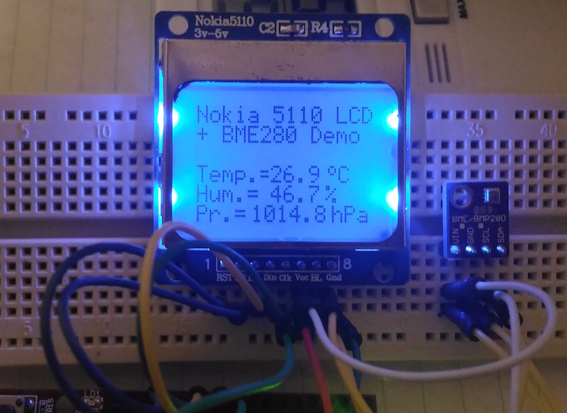
This project describes how to read barometric pressure, relative humidity, and temperature measurements from BME280 using chipKIT Uno32 to make a standalone weather station. The sensor readings are acquired over an I2C bus and are displayed on a Nokia 5110 LCD display.

Pingback: chipKIT Project 3: Easy Pulse Meter -Arduino for Projects