Breadboard module for 18-pin PIC16F microcontrollers (PCB version)
|
|
Because of their compact size, ease of use and many built-in peripherals, the 18-pin PIC16F series processors (PIC16F628A, PIC16F88, and now PIC16F1827/47) have always been my favorite microcontrollers. Many of my projects and tutorials written in this blog also use PIC16F628A and PIC16F1827 microcontrollers. As I will be using them more in the future too, I thought of making some PCB versions of my breadboard module for PIC16F628A with some modifications. I used Iteadstudio’s PCB prototyping service for this, and I would say the PCBs turned out really well for the price I paid. I used their 2 layer 5cm x 5cm service and got 10 PCBs for less than $15, including shipping to the United States.

Mini breadboard module for 18-pin PIC microcontrollers
Component layout and circuit diagram
The PCB dimension is approximately 5.0 cm x 3.5 cm and has got the following components:
- 18-pin DIP socket to hold an 18-pin PIC microcontroller
- 3-pin Ceramic resonator (4.0 MHz)
- Two tact switches (6 mm x 6mm, 2-pin type like this)
- 2-pin dip switch
- 4 resistors (two 10 K?, two 470 ?)
- 1 capacitor (100 nF)
- 2 LEDs
- 5-pin ICSP header
- Header pins for Vcc, Gnd, PORTA, and PORTB pins
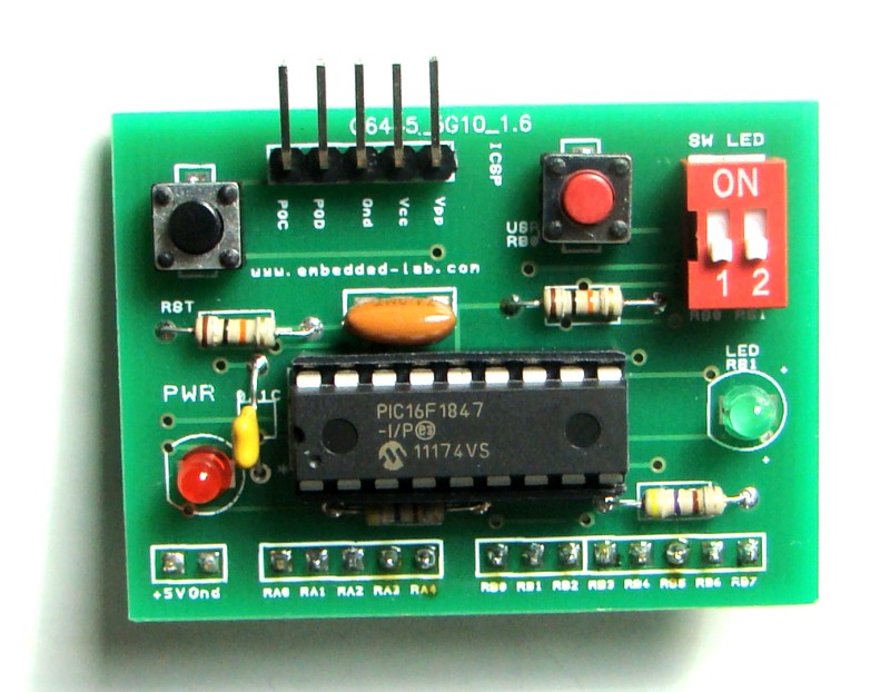
The layout of these components on the PCB is shown below. There are two tact switches on the board: one for reset and other for user input. Similarly, there are two LEDs: one for power-on indicator and the other for user output. The input tact switch and the output LED can be connected to RB0 and RB1 pins respectively through a 2-pin dip switch. The switch and the LED are useful for a quick test of the board. The microcontroller clock is derived using an external ceramic resonator having 3 pins with built-in load capacitors. PORTA (RA0-RA4) and PORTB (RB0-RB7) pins of the microcontroller are accessible for experimenting through header pins (male, female, or right-angled). A 5-pin header is also available for ICSP programming through a PICkit2 or PICkit3.

Layout of the components on the board
The circuit diagram of this breadboard module is provided below. It can also be constructed on a general purpose prototyping perforated circuit board just like my breadboard module for PIC16F628A.

Circuit diagram of the breadboard module
PCB design
I designed a two layer PCB for this project using the DesignSpark PCB design software, which is free and easy to use. It also lets you create Gerber files of your designed PCB. The top and bottom layer of the PCB are shown below. I have used a copper pour on the bottom layer to create a ground plane. It could be done for the top layer too.

Top view of PCB

Bottom view of PCB
The assembled module of the project is shown below.

PCB with all components soldered

Module can be easily plugged into a breadboard
Right-angled male header pins can also be used for accessing I/O port pins so that it can be plugged straight on one side of the breadboard (shown below).

Board can also have right angled headers

Running a test program (flashing LED) on the board
At last, I have got a few of these PCBs as extra. If you are interested to get one, contact me at admin (at) embedded-lab.com. It will be $4.50 (through Paypal) for one PCB and that will include shipping within the United States through USPS. Sorry, I won’t be able to ship it outside the US.
Update: Sorry, all the PCBs are gone!
Download Gerber files of the PCB design
|
|
pic16f1847 kit
muy buen excelente
Hi,
thanks for your work ,
can i know please what software you use to draw the circuit ?
regards
MS PowerPoint
Pingback: Placa de entrenamiento para microcontroladores PIC16F | Automatismos Mar del Plata