Hookup guide for 16×32 RGB LED panel – Part 1
|
|
RGB LED panels are a great way of displaying colorful texts, images, and animation. In this 3-part tutorial, I am going to demonstrate how to hookup our 16×32 RGB LED panel kit to an Arduino Uno board and run some demo sketches. Our 16×32 RGB LED matrix panel kit includes everything you need to connect it to an Arduino Uno board. The kit includes:
- One 16×32 RGB LED matrix panel
- One RGB connector shield for Arduino Uno
- One IDC cable to connect the RGB matrix panel to the RGB shield
- One power supply connector for the RGB matrix
Note that the power supply required to power the LED panel is not included in the kit. You will need a regulated 5V DC power supply with enough current sourcing capability (~2A) to power the RGB panel. If you could get the power supply with a 2.1mm x 5.5mm DC barrel output, that would be a plus. In case you don’t have such a power supply, we will show you later how to use a standard cellphone/tablet wall charger with an USB port for powering the LED panel.
Get this RGB panel kit from our Tindie store in USA!
Get this RGB panel kit from our Elecrow store in China!
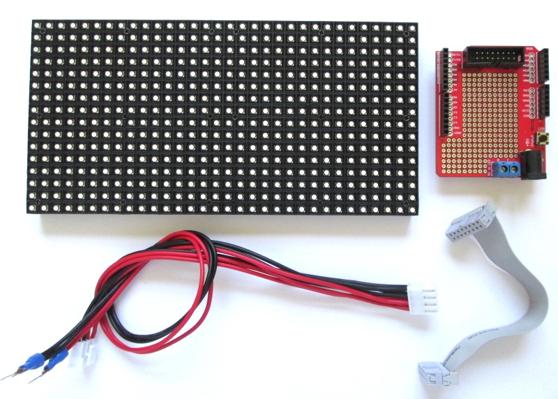
16×32 RGB LED panel kit
Step 1: Knowing the RGB LED panel
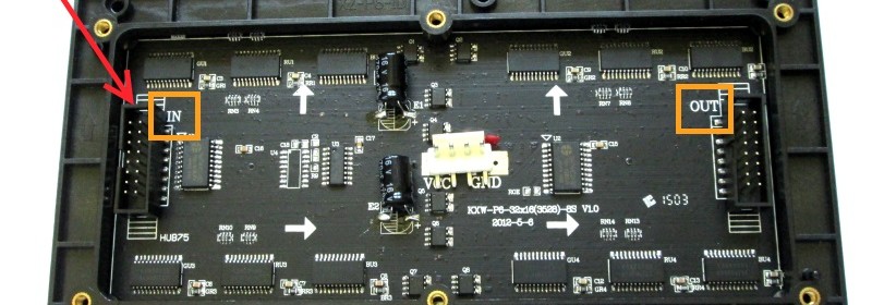
The front side of the panel contains 512 RGB LEDs arranged in 16 rows and 32 columns with a 6mm-spacing (pitch) between adjacent LEDs. The dimensions of the panel are are 192mm x 96mm (7.6”X3.8”). On the back side of the panel are the necessary row and column driver circuits. The LED display is controlled through 12 I/O pins (6 for data and 6 for control signals), which are accessible through a 2×6 IDC connector. There are two IDC connectors on back: one is marked as IN and other is marked as OUT. The Arduino I/O pins go to the IDC connector that is marked as IN. The OUT IDC connector is for cascading multiple RGB panels, which won’t be discussed in this tutorial.

IDC connector marked as IN is used to send the data and control signals to the LED driver chips
These LED panels are powered with a regulated +5V power supply through a 4-pin (2 for +5V and 2 for Gnd) polarized Molex-type connector located at the center of the panel on its back side as shown below.
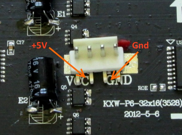
Polarized Molex-type connector for power supply
Step 2: Knowing the RGB connctor shield
The RGB connector shield is designed for Arduino Uno (and its compatible boards) for setting up easy connections between the Arduino board and the LED panel. A matching 2×8 IDC connector is available on the shield to connect 12 I/O pins (details of these pins are described later) to the LED panel’s IN port. A 2.1mm x 5.5mm DC barel connector is available to receive a high-current (2A) regulated +5V power supply from a DC walwart. This power supply is available for the RGB panel through a 2-pin terminal block. The figure below shows a close up look of the Arduino shield. The pins that are utilized by the IDC connector are marked with *. The free Arduino pins are 10 through 13, A4, and A5. Additional sensors and peripherals can be connected to these pins for user applications. A small prototyping area is also provided on the RGB connector shield to mount additional through-hole components.
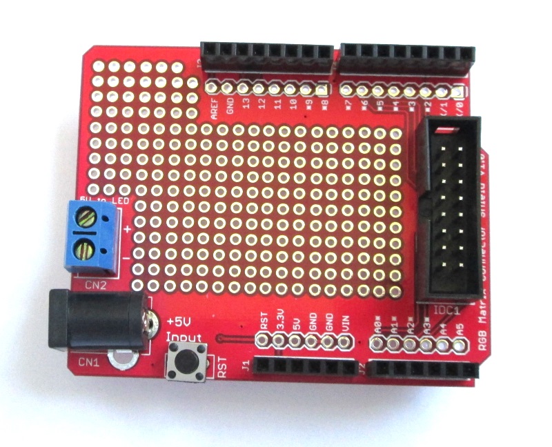
RGB connector shield
After getting familiarized with the RGB panel and the Uno shield, it is time to make the connections between the panel and the shield, which is described in the part 2 of this tutorial.
Continue to Hookup Guide Part 2
|
|