Inductance-Capacitance Measurement using PIC18 Microcontroller
|
|
When designing or debugging an electrical or electronics device, it is very important to know the values of the components that have been used on board. With a multimeter most of the components can be easily measured and identified but most ordinary multimeters do not have options to measure inductors and capacitors as this is rarely needed. However, without capacitors there are literally no circuits while complex circuits may have inductors in them. A LCR (inductor-capacitor-resistor) measurement meter can be used to determine the aforementioned components but usually such meters are pretty expensive.
Here, I will share a method with which we can measure inductors and capacitors with some degree of accuracy. For the purpose, we can use a common 8-bit microcontroller. I have used a PIC18F452. Of course, any other microcontroller will be equally suitable for the purpose as long as the calculations and procedures are maintained. We will also need a small external analogue circuit based on LM393 dual analogue comparator. This circuit is a simple Hatley oscillator. The idea is to measure the frequency or time period of the oscillator. When a new component such an inductor introduced to the oscillator, its frequency and therefore time period changes. We can then back-calculate component value.
PIC18F452 is an 8-bit PIC18F series microcontroller. In terms of hardware is much more capable than the popular PIC16F877A or PIC16F887. However, we do not need any other hardware apart from a capture compare module (CCP) and a timer. The main reason to use a PIC18F is its operating clock speed which is 40MHz.
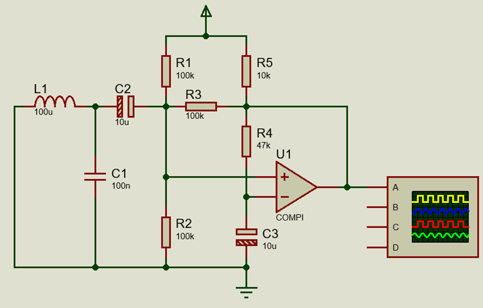
Schematic
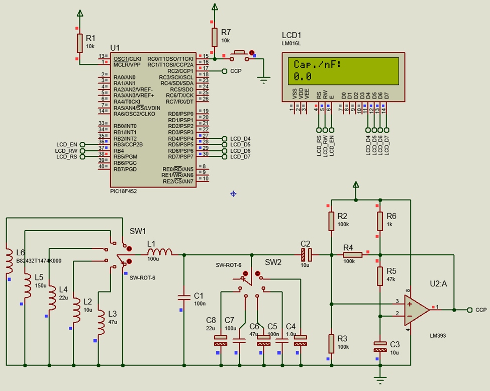
Components
As shown in the circuit diagram all the components would be needed. Components L2 to L6 and C4 to C8 are test components. These are present only in simulation and not physically. Rotary switches SW1 and SW2 are only use in simulation schematic and are physically not present. A 2×16 alphanumerical LCD is used for displaying info. And a button connected to pin C0 is used for mode selection.
Code
#include <18F452.h>
#device *=16
#fuses NOWDT, PUT, H4, BROWNOUT, BORV42
#fuses NOLVP, NODEBUG, NOCPB, STVREN, CPD
#fuses PROTECT, NOWRT, NOWRTB, NOWRTC
#fuses NOWRTD, NOEBTR, NOEBTRB, NOOSCSEN
#use delay(clock = 40M)
#include "lcd.c"
#define mode_button input(pin_C0)
#define C_cal_in_nF 100.0
#define L_cal_in_uH 100.0
#define pi 3.142
#define cal_delay 1000
#define scaling_factor_c ((10.0 / (4.0 * pi * pi * L_cal_in_uH)))
#define scaling_factor_l ((10.0 / (4.0 * pi * pi * C_cal_in_nF)))
unsigned int32 overflow_count = 0;
unsigned int32 pulse_ticks = 0;
unsigned int16 start_time = 0;
unsigned int16 end_time = 0;
void setup(void);
#int_TIMER1
void TMR_ISR(void)
{
overflow_count++;
}
#int_CCP1
void CCP_ISR(void)
{
end_time = CCP_1;
pulse_ticks = ((65536 * overflow_count) + end_time - start_time);
start_time = end_time;
overflow_count = 0;
}
void main(void)
{
short calibration_done = 0;
unsigned char mode = 0;
unsigned long t = 0;
double ref = 0.0;
double value = 0.0;
setup();
while(TRUE)
{
t = (pulse_ticks);
value = ((double)t * (double)t);
if(mode_button == FALSE)
{
delay_ms(60);
while(mode_button == FALSE);
calibration_done = 0;
mode++;
if(mode > 1)
{
mode = 0;
}
}
if(calibration_done == 0)
{
lcd_putc("\f");
lcd_gotoxy(1, 1);
lcd_putc("Calibrating....");
lcd_gotoxy(1, 2);
lcd_putc("Place no part.");
delay_ms(cal_delay);
lcd_putc("\f");
if(mode == 0)
{
ref = (value * scaling_factor_c);
lcd_gotoxy(1, 1);
lcd_putc("C.ref/nF:");
lcd_gotoxy(1, 2);
printf(lcd_putc, "%3.1g ", ref);
}
if(mode == 1)
{
ref = (value * scaling_factor_l);
lcd_gotoxy(1, 1);
lcd_putc("L.ref/uH:");
lcd_gotoxy(1, 2);
printf(lcd_putc, "%3.1g ", ref);
}
delay_ms(cal_delay);
lcd_putc("\f");
calibration_done = 1;
}
else
{
lcd_gotoxy(1, 1);
switch(mode)
{
case 1:
{
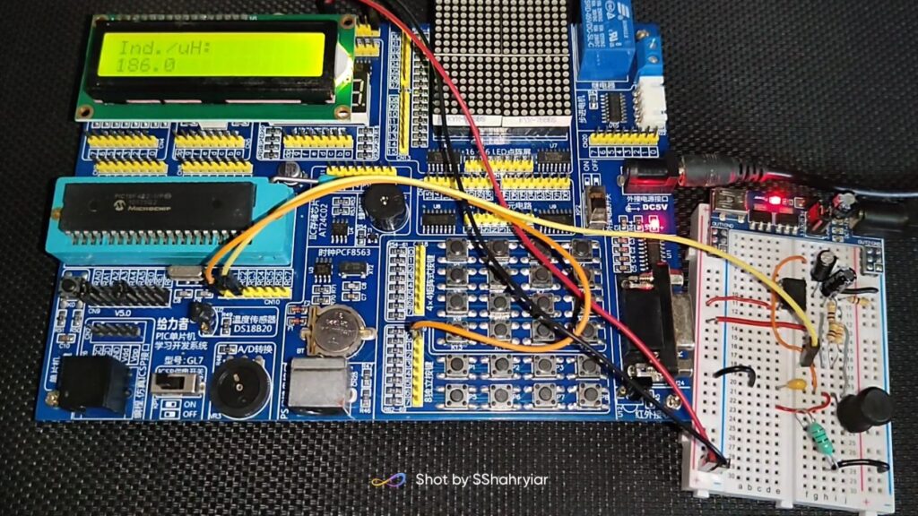
value = (value * scaling_factor_c);
lcd_putc("Ind./uH:");
break;
}
default:
{
value = (value * scaling_factor_l);
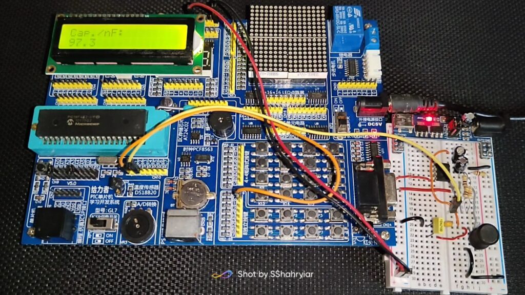
lcd_putc("Cap./nF:");
break;
}
}
value -= ref;
if((value < 0) || (value > 1000))
{
value = 0;
}
lcd_gotoxy(1, 2);
printf(lcd_putc, "%3.1g ", value);
}
delay_ms(100);
};
}
void setup(void)
{
setup_wdt(WDT_OFF);
setup_adc(ADC_OFF);
setup_adc_ports(NO_ANALOGS);
setup_spi(SPI_DISABLED);
setup_psp(PSP_DISABLED);
setup_ccp1(CCP_CAPTURE_RE);
setup_ccp2(CCP_OFF);
setup_low_volt_detect(LVD_43);
setup_timer_0(T0_OFF | T0_8_BIT);
setup_timer_1(T1_INTERNAL);
setup_timer_2(T2_DISABLED, T2_DIV_BY_1, 16);
setup_timer_3(T3_DISABLED);
set_timer0(0);
set_timer1(0);
set_timer2(0);
set_timer3(0);
enable_interrupts(INT_CCP1);
enable_interrupts(INT_TIMER1);
enable_interrupts(global);
lcd_init();
lcd_putc("\f");
}
Theory
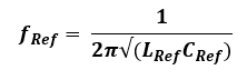
We know that:
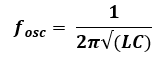
For a known set of L and C the equation above becomes:
We also know that the inductance of inductors adds when connected in series:
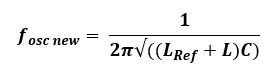
Similarly, the total capacitance of capacitors sums up when connected in parallel:
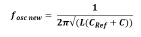
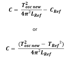
The above equation can be rearranged as follows:
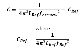
We also know that:

Thus, the above equation for unknown capacitor becomes:
The same is equation also holds true for unknown inductor too:
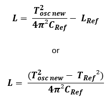
Thus, by knowing two different frequencies or time periods, the value of any unknown capacitor or inductor can be determined.
A PIC18F452’s CCP1 module along with Timer 1 is used to capture the oscillations coming out of a Hartley oscillator. With nothing unknown connected except the 100nF and 100µH reference capacitor and inductor respectively, the reference oscillation frequency is about 50kHz (about 20µs time period). Whenever a new component is added this frequency changes.
Explanation
Basing on the theory discussed, we would need PIC18’s high processing speed along with a timer and capture module. We would also need an LCD to display results. The setup function shown below highlights these modules and their settings.
 void setup(void)
 {
 …
     setup_ccp1(CCP_CAPTURE_RE);
 …
     setup_timer_1(T1_INTERNAL);
 …
     set_timer1(0);
 …
     enable_interrupts(INT_CCP1);
     enable_interrupts(INT_TIMER1);
     enable_interrupts(global);
     lcd_init();
     lcd_putc("\f");
 }
CCP1 module is set for rising edge capture. This means that CCP1 will capture Timer 1’s count whenever it senses rising edges. CCP modules in PIC microcontrollers usually work Timer 1 module and so its count is captured. Capturing two consecutive rising edges result in period measurement of incoming waveform. This is what we would need the most.
To further make thing work apparently in concurrent manner, interrupts are used. CCP1 interrupt is triggered when there is a rising edge capture and Timer 1 interrupt is used to keep track of timer overflows. The current and previous capture counts are stored while taking care of Timer 1 overflow. These would be used to determine time period. Timer 1 will rarely overflow because it would only overflow if the incoming waveform has very low frequency and this would literally never happen.
 #int_TIMER1
 void TMR_ISR(void)
 {
    overflow_count++;
 }


 #int_CCP1

 void CCP_ISR(void)
 {
    end_time = CCP_1;
    pulse_ticks = ((65536 * overflow_count) + end_time - start_time);
    start_time = end_time;
    overflow_count = 0;
 }
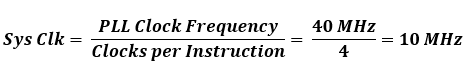
PIC18’s PLL is used to upscale an external 10 MHz crystal oscillator clock to 40 MHz. This is reflected in the fuse bit and clock settings.
 #fuses H4 ….

 #use delay(clock = 40M)
However, PICs usually take 4 clock cycles per instruction and so the effective system clock frequency is 10 MHz.
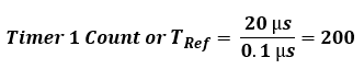
Thus, one tick of Timer 1 is:
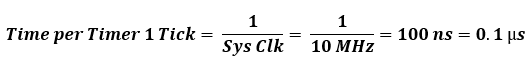
Thus, at the base frequency of 50 kHz (20 µs), Timer 1 would count:
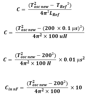
Since the reference inductor and capacitor values are know the following equations simply as:
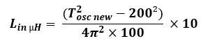
The same applies for inductor measurement too and the formula simplifies as shown below:
The fixed constants are defined in definitions on top of the code
 #define C_cal_in_nF         100.0
 #define L_cal_in_uH         100.0
 #define pi                  3.142
 #define cal_delay           1000

 #define scaling_factor_c    ((10.0 / (4.0 * pi * pi * L_cal_in_uH)))
 #define scaling_factor_l    ((10.0 / (4.0 * pi * pi * C_cal_in_nF)))
Now let’s say we want to measure 220nF. So, for this amount of capacitance, the oscillator frequency would be:
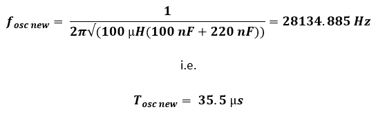
Timer 1 would count 355 counts while capturing this frequency from the oscillator.
Now if we back-calculate using the formulae shown previously, the capacitor is found to be:
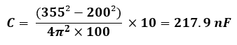
Yes, the reading is a bit off from actual value but close enough to actual value. The error occurs because timer counts cannot be anything other than integers. This error can be smartly compensated in code.
The push button connected to pin C0 is used to select either inductance or capacitance measurement mode. Every time the mode is changed, calibration would be needed. The calibration procedure is simple. We just have to leave our meter with nothing connected except the reference capacitor and inductor as shown the following circuit diagram. This is the Hartley oscillator and the core part of the entire device.
During this time, the reference component value is measured and saved. This value would be deducted during unknown component measurement. During calibration, the meter’s display would show instruction for not placing any external component.
After the calibration is completed, unknown components can be placed and measured accordingly. These are all what the program’s main loop does.
     while(TRUE)
     {
         t = (pulse_ticks);
         value = ((double)t * (double)t);

         if(mode_button == FALSE)
         {
            delay_ms(60);
            while(mode_button == FALSE);
            calibration_done = 0;
            mode++;

            if(mode > 1)
            {
                mode = 0;
            }
         }

         if(calibration_done == 0)
         {
             lcd_putc("\f");
             lcd_gotoxy(1, 1);
             lcd_putc("Calibrating....");
             lcd_gotoxy(1, 2);
             lcd_putc("Place no part.");
             delay_ms(cal_delay);
             lcd_putc("\f");

             if(mode == 0)
             {
                 ref = (value * scaling_factor_c);
                 lcd_gotoxy(1, 1);
                 lcd_putc("C.ref/nF:");
                 lcd_gotoxy(1, 2);
                 printf(lcd_putc, "%3.1g   ", ref);

             }

             if(mode == 1)
             {
                 ref = (value * scaling_factor_l);
                 lcd_gotoxy(1, 1);
                 lcd_putc("L.ref/uH:");
                 lcd_gotoxy(1, 2);
                 printf(lcd_putc, "%3.1g   ", ref);
             }

             delay_ms(cal_delay);
             lcd_putc("\f");

             calibration_done = 1;
         }

         else
         {
             lcd_gotoxy(1, 1);

             switch(mode)
             {
                 case 1:
                 {
                     value = (value * scaling_factor_c);
                     lcd_putc("Ind./uH:");

                     break;
                 }

                 default:
                 {
                     value = (value * scaling_factor_l);
                     lcd_putc("Cap./nF:");

                     break;
                 }
             }

             value -= ref;

             if((value < 0) || (value > 1000))
             {
                value = 0;
             }

             lcd_gotoxy(1, 2);
             printf(lcd_putc, "%3.1g         ", value);
         }

         delay_ms(100);
     };
Some time-proven good-old tricks have been applied in this code:
- Instead of measuring frequency, time period is measured. This saved one calculation step because frequency is inverse of time period.
- Rather than using math library, some values that need to raised by some power, is simply repeated multiplied. For example, the time period needs to be squared but instead it is multiplied by itself.
- Definitions have been used in order to identify some important constant values and reduce calculation.
- The use of global variables has been kept to a minimum. Although the code is nothing compared to the memory resources of the PIC18 microcontroller.
- Interrupt methods have been employed to make the program efficient and as less blocking as possible.
- Unused hardware peripherals have been reinitialized to reduce power consumption and other issues.
Demo
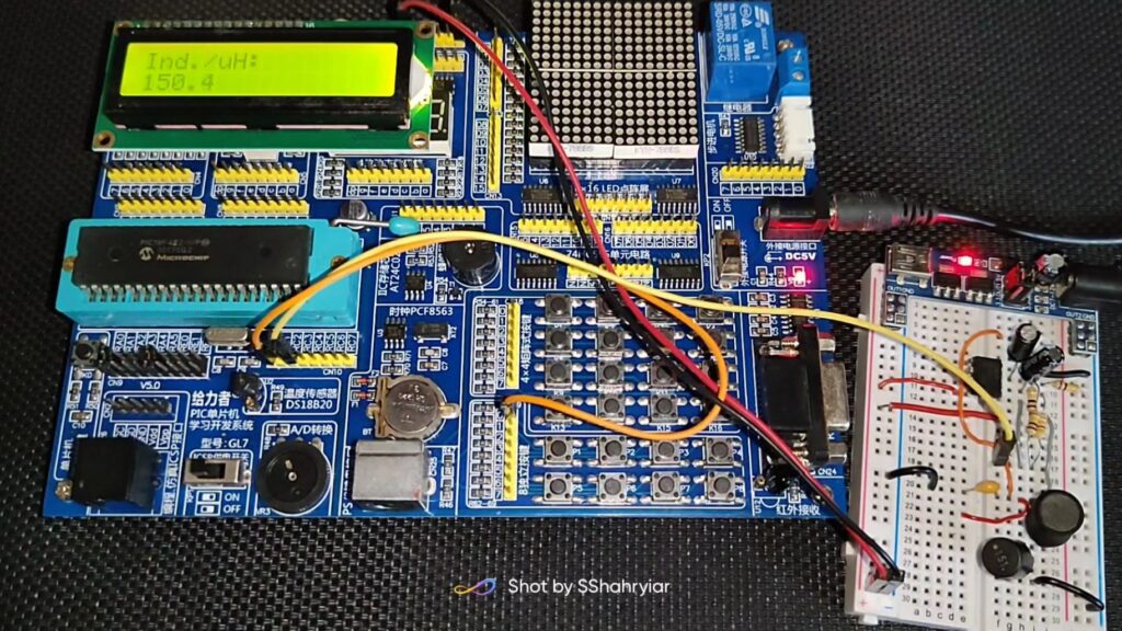
All files related to this project can be found here.
Happy coding.
Author: Shawon M. Shahryiar
https://www.facebook.com/groups/microarena
https://www.facebook.com/MicroArena
23.08.2022
|
|