Lab 15: Scrolling text message on an LED dot-matrix display
|
|
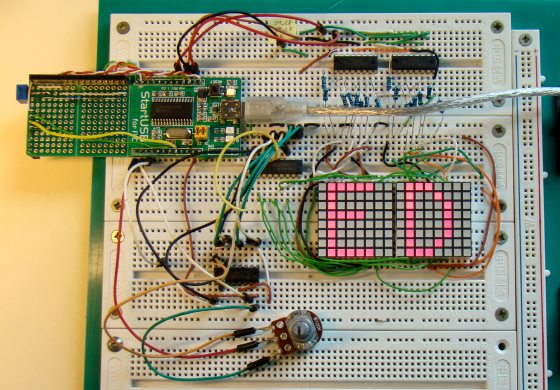
In Lab 12, we learned about the basic structure of a monochrome (single color) LED dot matrix and its interface with a microcontroller to display static characters and symbols. Today’s lab is its continuation, and we will be discussing on displaying a scrolling text message on a 16×8 LED dot matrix. The microcontroller used is again the same PIC18F2550 from StartUSB for PIC board. The 16 columns of the LED matrix are driven individually by two shift registers (74HC595), whereas the eight combined rows are driven by the decoded outputs from a decade counter (CD4017). In Lab 12, columns were scanned, but here we will be scanning across the rows and feed the column lines with appropriate logic levels. An analog input from a potentiometer is read by the microcontroller to determine the speed of the scrolling message. The technique will be demonstrated for right to left scroll, but can be easily implemented for scrolling in other directions. The program for PIC18F2550 is developed with mikroC Pro for PIC compiler.

Scrolling message display on 16x8 LED dot matrix
Circuit Diagram
The internal structure of LED dot matrix displays have already been discussed in Lab 12 and is not going to be repeated here. Two 8×8 LED matrices are used in this experiment. The similar rows (cathodes) of both are connected together so that there are 8 combined rows in total, whereas the columns are driven separately, and hence there are 16 columns altogether. The combined current of all the LEDs in each row sinks through a darlington-pair transistor array inside an ULN2803 IC. The 16 column lines (anodes) are driven by the outputs of two shift registers (74HC595) with current limiting resistors (220 ?) in series, as shown below.

Circuit diagram for displaying a scrolling message on LED dot matrix
Role of shift registers (74HC595)
The use of shift registers minimizes the number of I/O pins required to drive the columns of the LED matrix. For driving 16 columns separately, we need 16 I/O pins of microcontroller, however, with the use of two 74HC595 ICs, this number is reduced to 3. 74HC595 is an 8-stage serial-in, serial or parallel-out shift register, with a storage register. The shift register and storage register have separate clocks: SH_CP (pin 11) and ST_CP (pin 12). Data is fed serially into the register through DS pin (14) and is shifted on the positive-going transitions of the SH_CP input. However, the data in each register does not appear at the output pin of 74HC595 unless it is transferred to the storage register. This happens on a positive-going transition of the ST_CP input. 74HC595 also provides a serial standard output, Q7’ (pin 9) for cascading, which is needed in this experiment. The serial output of the first shift register is connected to the serial input (DS pin) of the second shift register, so that the 16-bit column data can be transferred serially through the DS pin of the first shift register. This requires 16 clock pulses on SH_CP followed by a clock pulse on ST_CP. The asynchronous reset pin (MR) is always pulled high (deactivated) whereas the output enable (OE) pin is permanently grounded (always enabled).
Role of counter (CD4017)
As mentioned in the beginning of this article, this time the rows will be fast-scanned from the top to the bottom, unlike the columns like we did in Lab 12. Eight I/O pins are required to scan 8 rows in sequence. You can use the PORTB pins of PIC18F2550 for this purpose. But if you think you will need them for some other purpose (some of PORTB pins have interrupt-on- change feature), you can use a port expander, such as CD4017, that will serve the purpose and require only two I/O pins of microcontroller. CD4017 is a 5-stage divide-by-10 Johnson counter with 10 decoded outputs and a carry out bit. The counter is cleared to zero count by a logical “1” on its reset line (15). The counter is advanced on the positive edge of the clock signal (pin 14), when the clock inhibit pin (13) is grounded. The 10 decoded outputs are normally in the logical “0” state and go to the logical “1” state only at their respective time slot. Each decoded output remains high for 1 full clock cycle. The carry-out signal completes a full cycle for every 10 clock input cycles and is used as a ripple carry signal to any succeeding stages. The 8 rows of LED matrix are sequentially connected to the decoded outputs, Q0- Q7, of CD4017 through ULN2803 IC that has eight Darlington pairs, each of which provides a ground path to sink the combined current of all LEDs in a row. At the end of every 8th clock cycle, the microcontroller will reset the counter by issuing a logical “1” to its Reset pin (15).
The microcontroller pins used for driving these signals for 74HC595 and CD4017 are shown below. A 10K pot is connected to RA0 pin of PIC18F2550 microcontroller that will control the speed of the scrolling message on the LED matrix display.

Microcontroller I/O pins for driving the LED matrix

Circuit setup on breadboard with StartUSB for PIC board
Software
If you are unfamiliar with how static characters are displayed on a LED dot matrix, I would recommend to read Lab 12 first. In row scanning, each row is selected for a very short time (about 1 ms) and the columns are fed with appropriate logic levels. By quickly scanning across the rows (> 100 times per second), and turning on the respective LEDs in each column of that row, the persistence of vision comes in to play, and we perceive the display image as still. The picture below shows the active LEDs in each row to display the character ‘A’ on a 8×8 dot-matrix format. This information for all printable ASCII characters (0-9, A-Z, a-z, etc) will be stored in a two-dimensional constant array CharData[][8] in the program memory of PIC18F2550.

8x8 dot matrix values for character A

Defining the column values for printable ASCII characters in 8x8 format
One question: “How would you find the right index of a particular character in this array?” The answer is simple. This array is created sequentially for ASCII characters starting from ‘Space’ (decimal value, 32) to ‘~’ (decimal value 126). So you need to subtract 32 from the ASCII value of the character itself to get the corresponding row index of CharData array. For example, if you want to display a dollar sign, $, its ASCII value is 36 (decimal). If you subtract 32, you get 4, which in fact, is the right row index of $ in CharData array (see above).
Now lets talk about the scrolling effect. We will also define a display buffer for storing the bit information of 16×8 LEDs in the matrix. It would be an integer array (16-bit) of size 8 (for 8 rows). The content of this array is what displays on the matrix. The picture below shows the bit values of the buffer for blank display, i.e., all LEDs are turned off.
8x16 bit DisplayBuffer
Now lets consider the case of displaying a message that scrolls from right to left. For displaying a character on the matrix, you need to switch among the rows very fast while feeding the column lines with appropriate logic levels (character specific) for each active row. If you want to move the character from right to left, you have to shift the column values for all rows in to left direction with an appropriate amount (Shift Step). Once the character has been shifted sufficiently, you can start feeding the column values of next character in the message. In each shift, you need to update the display buffer. The formula for updating the DisplayBuffer that would create scrolling effect from right to left is,
DisplayBuffer[i] = (DisplayBuffer[i] << ShiftAmount) BIT OR (CharacterRow[i] >> (8- ShiftAmount)
e.g., Suppose, the display is initially blank and you are scrolling character ‘A’ from right, one column at a time. If you see the matrix pattern for ‘A’ in one of the pictures above, you will see that the first three columns from left are all blanks, so nothing would appear on the 16×8 matrix until the fourth column (ShiftAmount = 4) is shifted into the DisplayBuffer. The picture below shows the stage where the initially-blank DisplayBuffer has already been shifted to left by 7 columns (ShiftAmount = 7). DisplayBuffer for row 1 was initially all zeros, ‘00000000 00000000’. The new DisplayBuffer for the first row after the character ‘A’ is partially loaded (up to its 7 columns) is ‘00000000 00000111’. This can be obtained by first shifting the previous value of DisplayBuffer to left by 7, which still gives DisplayBuffer[1] all zeros. The first row of character ‘A’ in an 8×8 matrix format is ‘00001110’. If you shift this right by 8-7 = 1 step, we get ‘00000111’. If you bit-OR this with the new DisplayBuffer[1], you will get ‘00000000 00000111’.
The value of ShiftAmount must be increased sequentially up to 8, after which the 8×8 character is fully loaded in to the display buffer. Then, ShiftAmount restarts from 1 again and starts loading the next character from the right, while the display buffer itself shifts left. This continues until all the characters in the message are loaded.

Display Buffer after shifting 7 bits to the left
The following routine serially feeds the two shift registers with a 16-bit column value.
void send_data(unsigned int temp){
 unsigned int Mask = 0x0001, t, Flag;
 for (t=0; t<16; t++){
  Flag = temp & Mask;
  if(Flag==0) Serial_Data = 0;
  else Serial_Data = 1;
  SH_Clk = 1;
  SH_Clk = 0;
  Mask = Mask << 1;
 }
// Apply clock on ST_Clk
 ST_Clk = 1;
 ST_Clk = 0;
}
And, the following code does the scrolling of message on to the matrix display. The value of shift_step determines how many columns you want to shift at a time. I set it to 1.
for (k=0; k<StringLength; k++){
  for (scroll=0; scroll<(8/shift_step); scroll++) {
   for (ShiftAmount=0; ShiftAmount<8; ShiftAmount++){
    index = message[k];
    temp = CharData[index-32][ShiftAmount];
    DisplayBuffer[ShiftAmount] = (DisplayBuffer[ShiftAmount] << shift_step)|
   (temp >> ((8-shift_step)-scroll*shift_step));
   }
  speed = 10+ADC_Read(0)/10;
  for(l=0; l<speed;l++){
   for (i=0; i<8; i++) {
    send_data(DisplayBuffer[i]);
    CD4017_Clk = 1;
    CD4017_Clk = 0;
    Delay_ms(1);
   }  // i
  CD4017_Rst = 1;
  CD4017_Rst = 0;
  } // l
  } // scroll
 }
You can download the complete mikroC project files for this tutorial from the link below.
References:
Beginning Arduino (book) by Michael McRoberts has a very good description of creating animation on LED dot matrix display.
|
|
i am not getting the output of the uln2803 as similiar to its input…i am selecting the column using the uln..can you please help
The ULN2803 device’s output is open collector. To get output from this IC pullup resistors are required on its out put side. please note, its outputs are inverted. We must give logic high on its input side.
Try this i hope you will get proper output.
I constructed your circuit using the 18f2550 pic and used the scrolLED.hex file to replicate your results. However, the first row showed a very faint version of the last row and rows 2 through 8 showed the correct scrolling sign of rows 1 through 7. I checked the circuit at least 3 times and could not find a problem. Do you have any idea what is wrong?
Thanks.
Vorreì chiedere che può fare il programma per il pannello display “sure electronics p4 32×8 3208 red led dot matrix unit board spi like” .
Vorreì aggiungere al sistema anche pulsanti e i potenziometri. Esempio: premendo il 1° pulsante si accende il display col nome memorizzato e anche scorrerà per un tempo di almeno 3o secondi, e cosi via per altri pulsanti che all’occasione servono per richiamare la voce programmata.
Vorreì sapere avere come aggiungere due potenziometri: uno che regola la velocità di scorrimento ed un secondo che regola solo il tempo. Se puoi? grazie
cordiali saluti
Sir, thank you for this tutorial. I tried simulating with proteus, it scrolled well but the chacters are in 5×7 blocks. what could be the problem Sir?
You can also save one pin by tying Q8 (9) pin of CD4017 to its RESET (15) pin. 😉
Good work and more grease to your elbow. The Tutorials have been so helpful and valuable especially for me. I say THANK YOU. Please, i have designed the scroll display circuit with 16f1847 and it worked perfectly well. But how do i change the text to be displayed in the default message. I have tried modifying the code given but the display has been null. Please what or how can i change the default code without connecting to a computer system.
Good day sir, am intrested on your scrolling text massage on led 8&40, but the problem is that i want to replace the pic16f1847 to pic18f2550, if it can, can u write the source code and hex file and circuit diagram for me, and i will also like you to make the text on led after displayed at end, the text will fly and comes up and dwon and pus for some secons. thanks i nee your reply on my email, chekwubemartins@yahoo.com
Hai hi have used ur code scrolling is coming but instud of letter,block is coming plz help me
dear sir
please give me answer..
digital display circuit diagram and with program
equipment use and value of equipment…
i hope positive answer..
Your project is so nice and I make it from scratch using PIC16F877A and test your code with small modified to remove ghosting led and now work fine.
But I would like to scroll up and down and more Animation if possible.
I am trying but I don’t get good result.
Any help I will appreciate that.
Best Regards
hosam matar
Plz send me this c code for pic 16f877a i need you help. My email ID is maliksaad84@gmail.com and if possible proteus too. It will be honoured
See amazing LED project here: http://kck.st/1Oi2sHC
Simply and affordable…
Can u mail me 16*128 moving message using leds
Pingback: which Led Mtrixdriver IC i can use ?
Hi Sir. Thanks for your great work. sir,you seem not to answer the question why the matrix does not display the character correctly, even though it is scrolling well,when simulated on proteus.I am also experiencing the same challenge.pls,help out sir.
how would you go about adding a microC compiled .asm of .hex file into proteus and still come with the microC liblary files. please any assistance on this is appreciated
Sir will u able to send me the code for the same project in 8051. please sir.
its urgent sir
sir I want PIC 16F877A program for same this project
Na minha simulação no protesus, a matriz 8×16 apenas imprime e rola blocos, nao rola a mensagem de caracteres. O que seria preciso mudar ??
Precisas de colocars resistencias pull up nas linhas da matriz entre os pinos 11 a 18 do uln2803 a vcc para a simulação funcionar. Se montrares o circuito já náo precisas delas.
O proteus não simula bem o uln.
Sir, Why it is not working on proteus….Scrolling Effect is okay…….But it is displaying blocks in place of characters….
Hello. The code is not displaying the characters on proteus. What might b he reason? And pls has anyone actaully dine this on proteus and it worked?
Pingback: [AVR] Please Help Me with LED sign board C Program
Pingback: [PIC] pic16f877a scrolling txt help
hello man. thanks god i found this, im doing this for my FYP. im just need a circuit diagram . can u help me please. the circuit diagram for the last picture under the youtube. Pleasee help me. im begging youu
…Hi RB, your work here is great and has been helpful. I’m building a similar work but with an Anode-Row type of matrix display, I was successful at that. However, adding four more displays to the design is quite a challenge to me with respect to the source code. Kindly help me with necessary adjustments, all I know about coding for PICs are from this great site. Thanks a lot.
Check out this one:
http://embedded-lab.com/blog/?p=4717
sir,i want work on 8×88 led dot matrix display.please help me by sending circuit diagram & program.it be help heipful
sir , Ineed a project scrolling messagedisplay .16/160 led and mcu avr at89c55wd based please help?
Hi,
i implement the lab 12 using two 74595 and Tiva C series, but i try to implement the Lab15 using two 74595 but i fail,i cant scroll the characters. can anybody have the idea to implement this?
your 16×8 dot matrix project is excellent..
sir how can i convert 16x 8 to 40×8 dot matrix font flowing your code??
plz help me sir….
–
dear sir,
your 8×40 dot matrix project is excellent..
sir how can i convert 8×40 to 16×40 dot matrix font flowing your code??
plz help me sir….
your 8×16 dot matrix project is excellent..
sir how can i convert 8×16 to 8×40 dot matrix font flowing your code??
plz help me sir….
Hello.
first of all thank you for the tutorial most informative.
i’m currently working on 8×80 led matrix marquee,i’m using PIC 16F877,74HC595 shift registers and 4017 counter.
i’m able to scroll alphabet,symbols and letter using SPI but i couldn’t get your code to run correctly and display a custom message.
can you help me use your display technique but with SPI bus of the PIC MCU ?
thank you in advance
sir i want to implement the same project with 8051 micro controller so please guide me with that..what changes i need to make in the programing? can u please guide me for that sir?
sir i want to make16x160 led moving massage display project with 8051 micro controller so please guide me with that..what changes i need to make in the programing? can u please guide me for that sir?
Dear Sir,
I am a student.i am interested to led matrix display.your matrix project very use full for us.sir i
have a little question about display buffer for scrolling.i am not clear this fact.
DisplayBuffer[ShiftAmount] = (DisplayBuffer[ShiftAmount] <> ((8-shift_step)-scroll*shift_step)); // what will be output of this line
can u help me on the initialization of variable temp
Hi all,
can we have a fixed display and do you have sample code for fixed display ?
Best regards
Sir , am working scrolling message on notic board then please can you help me which IC I use for deriving the LED matrix.
Thanx for giving info
sir,I am writing a project on scrolling message . can you please help me with code and circuit using 89c51 MCU. Thanks
I would like to make a longer display. ..
its good to see
i want to make a moving matrix display with pic-microcontroller..i use pic-16f72 and my compiler is micro c.
please give me dot matrix coading with prutious simulation…
sir i am not a big programmer,but i want to make a medium moving matrix display of pic microcontroller…
please help me sir
hey dear all friends,
plz kindly send me a codes to display (0-9) in dotmatrix display programming or best link those wepsites are help me thanks
Regards
kamran ali shaikh
+923007089928
sir i tried running your code on proteus but the characters are not displaying b glad if you can help
Very nice tutorial !
With a few modification in code and fonts(I used 5×7 Fonts) i have implemented this using ATmega32(AVR. How I can post my work so that other can get benefit.
can you send me avr c file ,it is helpful for me . my mail :shailesh4440@yahoo.co.in
Great job!
well i think we can implement the same using 5×7 dot matrix.
can you suggest me what changes i need to apply on the logic if i have the 5×7 fonts ready.
can anyone please tell me that in the command:DisplayBuffer[ShiftAmount] = (DisplayBuffer[ShiftAmount] <> ((8-shift_step)-scroll*shift_step)
what does scroll*shift_step written for.
i am seriously unable to understand
please help me out with this
hi anyone can give me the schematic and coding for arduino drive 24×8 led dot matrix…i have find many, but not succeed to find the best..
Hey Ya,
Can you please guide me get the delay of3 hrs and 18 hrs in MSP430 micro controller(MSP430G2231).All the connections are done as shown above in LAB15.But only the microcontroller is different.I am using MSP430 Launchpad.
I am using Embedded C for coding.
Hey Guys,
Can you please guide me get the delay of3 hrs and 18 hrs in MSP430 micro controller(MSP430G2231).All the connections ARE done as shown above in LAB15.But only the microcontroller is different.I am using MSP430 Launchpad.
Pingback: Using 74HC595 and CD4017 to expand IO of MCU for driving a scrolling dot matrix display
Sir that’s a good work. But I have problem with the simulation, though I’m not using startUSB for pic but Proteus instead.After compilation on microC pro for pic and simulation on Proteus,the message can scroll from left to right but the characters are not properly displayed. In fact they are like graphic with undefined pattern.Is there any thing I can add when loading the hex file on the MCU? In case any body want to send any help,please do so to this email:fetenchris@gmail.com
Sir Eng.R-B i have cracked my head to see that the 8×16 dot matrix could be extended to like say 8×32 but i could not get it done please help.
See here: http://embedded-lab.com/blog/?p=4717
sir i using this scrolling program and perform with proteus..the words not clear in dot matrix ….. sir help me
Hi,that’s good work.But I have problem during simulation on proteus,though I am not using startUSB for pic.During simulation it can scroll but the display is not what is written in the char message, in fact the display is like a graphic and it is not readable.please any help.
hello there,I want to display static characters ABC with 8*8 dot matrix,can anybody help me to do so?
Thanks
Please sir, I use microCPRO for pic and protues to compile and simulate the scrolling message on 8×8 dot matrix display. It can scroll from right to left but characters are not not well written in fact they were like graphic display.Help me.
Thanks for this project Mr. Raj!
My question is : How can i do to display the number 9 without the scrooling effect?
is there any way?
your answer is greatly appreciated
thank you!
Hello,
thank you for this beautiful project,
but i have a problem :
I have used your code with 4 matrix 7 * 5
Columns 1,2,3 and 4 are never on
do you have an idea ?
My code :
void envoi_data(unsigned long int temp){
unsigned int Mask = 1;
unsigned int t;
unsigned int Flag;
for (t=0; t<20; t++){
Flag = temp &Mask;
if(Flag==0) Data = 0;
else Data = 1;
Clk = 1;
Delay10TCYx(0);
Clk = 0; // Clk à 0
Mask = Mask << 1;
}
Can I use 3 shift registers instead of using 2 shift registers and a CD4017 to two 8×8 Led Dot Matrix?
dear admin…
may i know? what you use software for the compile file .c , thx bro
HI Sir very nice projects and Explanation.can u help to convert Code in PIC basic ??
Thank’s
hi nyacuma would you please share your 8×64 project plseeass benel78@yahoo.com
Awesome WorK !!!
I have tried ur code buddy but I am having a problem at the time of scrolling effect ,., it display the image perfectly, when it turns to scroll ,,, the character is gone , and displayed again, with one shift step../ ,.
I hope u get it ., 🙁
first of all this nice blog and the tutorials are explained very well.I appreciate ur good work.
Now i have some questions???
1.what if i want to scan the column instead of row scanning???Coz in Bangladesh electronics market we only have rows(common anode) type dotmatrix.
2. How to change this program for column scan and scrolling the message??
3. Is there any necessary to change the circuit diagram again??? What it should be for column scan??
Please Replay. Thanks once again. Or mail me at
mahmud.ibrahim021@gmail.com
u have proteus simulation of this ??
Muito bom o tutorial, mas não consegui fazer a simulação do código… e também gostaria de incrementar mais colunas, como devo fazer…
Hi guys, anyone that can help with the scrolling message display for 8×64 leds? I’m working on the project. Please. here is my email where you can send me the necessary files. alawode_basitolakunle@yahoo.com. Waiting for your response soonest. Thanks.
anyone successfully finish the project who can help me? the row 1 is showing instead of the 8th row, and 8th row is showing instead of the 1st row.
thank you so much to help me!
marC:)
hi guys, please I’m also working on the scrolling led display. Nyacuma, can you share your project with us.
Anybody that can help with 8×64 display code. I’ll greatly appreciate it. thanks.
Hi guys, I tried simulating it on proteus, But its not displaying. I don’t know what’s wrong with it. Any idea. Thanks.
Nyacuma, can you please share your project with us. I’m also working on the same project and I working on the same project. Thanks.
Here’s my video : https://www.youtube.com/watch?v=YDGGMVMeS4U
ULN2803 is for row, so this is not 74HC595 is responsable for mixing row 1 and 8 ?
tell me what you think?
thank you!
marC:)
Hi Raj!
I have spent the day soldering this project, it is scrolling the the first row is showing and the 8th row, i did exactly everything what you mentionned. i don’t understand, i dont use start usb for pic.
I’m using crystal 4 mhz.
I really count on you.
thank you!
marC:)
Hi Marc,
Which microcontroller did you use and what is your circuit diagram? Can you send me your program? You have my email address.
Thanks for the answer Raj!
I would like to know : i did the lab 12 experiment with resistor for each row of the matrix why in the lab 15 : we have to put resistor for collumn not row ?
is the dot matrix in this experiment is commun cathode??
i have commun anode one?, does it works with this experiment too?
thank you!
marC:)
Raj? What dot matrix do you use? do you have the number of the component?
thank you!
marC:)
Marc,
I used these ones:
http://www.futurlec.com/LED/LEDMS88R.shtml
Does it requires a crystal? it’s not very clear on the page ??
thank you!
marC:)
hi Nyacuma, I am doing the same project of LED scrolling for education purpose & I want to add more displays. But I cant understand how to modify the codes.so, can you help me in coding this project….
Thank you.
tharakaxe@gmail.com
Great and helpfull tutorial.
Thank´s a lot !!.
Hi guys, I just completed my 8×64 LED matrix project. I incorporated a code for PS2 keyboard which utilizes the 256 DATA EEPROM on a PIC 16F88. My circuit is very lean. It’s only the 16f88, a ULN2803a,and 8 74HC595 shift registers!
Can you share more details of your project with us?
CA dot matrix Raj?? or CC matrix type??
thank you!
marC:)
Pingback: Berkenalan dengan Decade Counter CD4017 | ? Emanuel Setio Dewo ?
aiuto, come posso fare visualizzare su led matrix la temperatura interfacciando la sonda ds1820
grazie attendo risposta
Hi there. Thanks for great project!
I am working on 5 displays of 8×8 matrix dot. May i know what is the modification in the software? Thanks in advance.
Regards,
MZBI
if any one like to help me…. i used micro C and CCS C compiler ..i relay like to make a led sign board.dear sir help me to implement a led sign board,replay soon sir…my email is
shan2012mec@gmail.com
thank you very much sir.
dear sir i made this as same as u show in diagrams and i convert the micro c code by replacing pic16F877A …code is working but the thing is some points were at wrong positions.cannot understand whats happen. help me to solve the problem..if i add S character top part was missed…help me dear sir..thank you very much sir.
regards,
shan
sir,i need a circult diagram for 20×6 led matrix
Hello!!!
First of all thanks for such a wonderful tutorial.
I am also using Led Matrix 8×8 And its working perfectly when used directly with PIC18F4550 pins directly.
But when i use 74HC595 to drive my Led Matrix my Display is not working good.
Almost all led’s are glown (the one which are supposed to glow are glowing good, but rest are also glowing)
Have a look at this video.
http://www.youtube.com/watch?v=BFnZLPzIu7o&feature=youtu.be
What may be the possible cause of this.
I am using ULN2803 and its input is connected to PORTD of PIC18F4550.
I am using 220ohm resistance for connecting 74hc595 and led matrix
The video above is under that configuration.
Changing this to 10K almost finishes the display and then to 1k ohm i am not getting very good result, just 10% better than that with 220ohm resistor.
Please help me how can i solve this problem.
🙁
Check your circuit and make sure there are no short circuits between pins. What platform are you using? Do you have the circuit diagram and software of your project?
Last day I made this project & it is working extremely good.But when i use 24×8 LEDs and make changes in code like here,the circuit was not working.What should be the problem…?
void send_data(unsigned int temp){
unsigned int Mask = 0×0001, t, Flag;
for (t=0; t<24; t++){
Flag = temp & Mask;
if(Flag==0) Serial_Data = 0;
else Serial_Data = 1;
SH_Clk = 1;
SH_Clk = 0;
Mask = Mask << 1;
}
// Apply clock on ST_Clk
ST_Clk = 1;
ST_Clk = 0;
}
Dear sir , I have need a MPPT SOLAR CHARGE CONTROLLER
Circuit diagram using pic16f676 pls help me for hex code/c language and circuit diagram example a 24 volt battery system
Thanks
Ur faithfully
Faidul islam
Bangladesh
Necbd@live.com
Pingback: Why this 8X8 Matrix not working?
pls i need your help profer solution of making an 8x32or bigger matrix board on proteus using 16f877a pic and 74164 shift register. i tried cascading an 8×16 but the letters are duplicating or mirroring in the new matix pls help me out
Is it absolutly necessary to have the startusb for pic to do this project? or a pic18f2550 pic is okay with the programming? do i need different config for mikro C PRO ?
thank you!
marC:)
Not really, you can use PIC18F2550 for your project.
@Nyacoma plz send your code and protius simulation…plzzzzzzz brother…plzzzzzz
hi,
i saw your program.the problem i am getting in this is that the characters are not formed properly.i mean to say that the for a straight to be displayed a single dot is only displaying on the matrix.i am using mic at89c51 microcontroller.please help me out .i have tried a lot bt did’n get any solution.
i will be thankful to u provide me your suggestion.
thanks.
Thank you,
Sir will u able to send me the code for the same project in 8051. please sir.
Thank you again.
Manikandan A
@ Nyacuma pls can u share with us, how u accomplished the 8 x 64.
thank
Hi all! I have just finished writing code for an 8×64 led matrix. what i did was just learn from the above project.it is scrolling nicely. Am proud of eng. Rajendra Bhatt and MIKROE for I first learnt coding by studying this 8×16 scroll. I’ve doe away with the 4017 and instead am using a whole port. i’ve changed the SPI and written my my own. I’d never
have done it without without building on eng.Rajendra Bhatt project.
How to make this project using 89c51 because when i write this code for 89c51 after changing pin configuration it does not work correctly on hardware.
HI ALL
GREATE PROHECT AND I WISH THAT YOU HELP ME
IF I WANT TO DO THIS PROJECT WITH OUT ULN2803 (DIRECTIY FROM 4017 TO MATRIX ) HOW I CAN CHANGE THAT CODE
BECAUSE THE DATA OUT IS SHIFTIED
THANKS
Sir, Can you explain further how to configure oscillator( Criztal). I can’t buy 48MHz criztal because it is not available in the market. In this experiment did you use internal oscillator or something? How can configure it?
dear all,
I need to have some software to enter “text” or “letters” into the 16f628a type pic.
and also the data path should be through the Gnd. & the 3rd pin of the RS232 port. if anyone can give me help???
i am looking at the inbox of my g-mail
E-MAIL: randinu2007@gmail.com
with kind regards,
Indika – FROM SRI LANKA
HI R-B,
As u help others plz help me too.
I solved my problem I am able to work with 8×8 matrix .
Can u suggest me what I have to make changes to work with 8×32 matrix.
I am following ur code refrence with some changes.
Regards,
KCP
Also I am using the mosfet along with shift register to control columns…….
HI R-B,
I working on similar project butwith only one 8×8 display can u suggest me changes in your program ..instead of decade decoder I am using demultiplexer canu suggest me solution here Ipost my code…
plz rep ASAP.
Hi, this is a great tutorial. Can you tell me if one uProcessor such as this can be used for a 35×7 matrix (i.e 7x 5×7) matrix?
Thanks
Hello, R-B,
I want to ask, if I want to extend it to 24 columns/32columns. which one in the programming I should change? At the 17th column till 24th column, the letter is in inverse order.
Hi..
how to add more displays to this?
thanks i almost get it
Hi i have tried and completely made this project on proteus 7.8 and Micro C compiler …. but characters not appears only 5 column 8 rows are scrolling . is that because of 4017 ? or ? if you want let me show you video record.. help me
vary good …. i want project display message on lcd( using dot matrix and mikro C ) ???
Hello,
I want to ask what to powered it, because I am doing it and only 32×8
and RGB.
What source is used, and knew we would advise that what I use myself.
I saw the video and that is much resembling what i want to do. I have downloaded the code, but i want to ask two things:
1- What should i do with code when I have not to use potentiometer?
2- What to do with the circuit when i have to use 5×7 matrices rather than 8×8?
Sir
I don’t know how ran this program in mikroC softwere
sir ,
can i build this project with 16f628 pic/89c51 mc and can i add 10 or more displys with dis circuit.
@R-B
LOl thank you i’ve just realised after using a ps/2 keyboard, that i asked a stupid question looll
thank you again
Pingback: How to have 50 I/O pins using 16F877A
Hi
thank you for your effort, it’s really a good work, i did some little change to addapt it to a 8×8, i just wanted to know how this code pick the bits from the buffer
Exemple : if the letter is ‘A’ how did this code take the right bits from the buffer, how did he know that ‘A’ is equal to {0b00001110, 0b00010001, 0b00010001, 0b00010001, 0b00011111, 0b00010001, 0b00010001, 0b00010001}
i just want to understand the code better, thank you again
@redmatrice,
It is described in the software section.
Dear Sir,
Can I know the differences of adding 5 displays and 2 displays dot matrix in software part ? Which part of coding have to change?
I see…
But i met a problem again..The words display unsequenced..The words at the 8th row is jump to the 1st row..and the 2nd row jump to the third row and so on..
Any idea about this?
I can’t get the output T_T
May i know why the
ST_Clk = 1;
ST_Clk = 0;
Why must from 1 to 0? Is it the Low-to-High Transition that mention in the datasheet of 74HC595?
@Apple Ching,
The data get shifted on positive-going transitions (Low-to-High). Since ST_Clk is 0 by default, you need to make it High first to get data shifted, and back to Low again for next shift.
Friend excellent project to help me understand how does it do <t16 in which part of the program is to extend this solution I would at <32 tried t <32 but flows from right to left <for 16 more columns.
Thank you.
I can not find the solution only you can help me.
thanks and congratulations by Salvatore
I want to add Total 8 displays in one line (8 x 32).So that i can display 8 letters at one time. i will need to add 6 more shift registers and what changes will i have to make in the software? should i change the for loop t<32. Also will the memory be enough to display 8 characters. Please help. Thanks .
void send_data(unsigned int temp){
unsigned int Mask = 0×0001, t, Flag;
for (t=0; t<32; t++){
Flag = temp & Mask;
if(Flag==0) Serial_Data = 0;
else Serial_Data = 1;
SH_Clk = 1;
SH_Clk = 0;
Mask = Mask << 1;
}
// Apply clock on ST_Clk
ST_Clk = 1;
ST_Clk = 0;
}
HELP HELP FRIEND
@Salvatore,
Adding 8 displays would be similar in hardware but the software part requires more modifications. The technique described here will not work. I am working on a similar project but with 5 displays, and I will be posting it soon.
Voglio aggiungere Trovati 8 mostra in una sola linea (8 x 32). In modo che io possa visualizzare 8 lettere in una sola volta. ho bisogno di aggiungere 6 turni più registri e quali cambiamenti si devo fare nel software? aiuto per impostare la formula dalla 32 colonna a 0 colonna
Do you have the code for 89S52 or MCS51 series ?
I want to connect 1 matrix 8×8 into port 1 and port 3 89S52, just for test 🙂
Did you use RA0 in this circuit diagram??
Why the coding need to be declare the RA0 as input?
Read from top to bottom once again, it is mentioned in the article.
Thanks a million. Yesterday I completed this 8×16 Led matrix and I was overjoyed seeing it spring to life the first time I powered it. I was not able to get Mikroe USB board but I used a PIC 18f452 ( at least what is available here in Kenya. I would like very much to see the 64 columns of LEDs I made a month ago do the same. Again THANKS!
hi nyacuma i made a 8*64 using pic16f88,where did u buy f452,masimo or project shop and how much?my email address is kihiudn@gmail.com.im looking forward to get your reply so that we can share more
Pingback: 8x8 Dot Matrix Display with '595 shift register problem
Pingback: (PIC)Designing 8x8 matrix display with Darlington transistor arrays.
Hi, thanks for the detailed tutorial although there’s no line by line comments. I’m planning to build this one too and I did this exactly in Proteus but why is it not working? I used PIC18F4620. The characters shown can’t be understood.
Dear Sir,
I want to add Total 8 displays in one line (8 x 64).So that i can display 8 letters at one time. i will need to add 6 more shift registers and what changes will i have to make in the software? should i change the for loop t<64. Also will the memory be enough to display 8 characters. Please help. Thanks .
void send_data(unsigned int temp){
unsigned int Mask = 0x0001, t, Flag;
for (t=0; t<64; t++){
Flag = temp & Mask;
if(Flag==0) Serial_Data = 0;
else Serial_Data = 1;
SH_Clk = 1;
SH_Clk = 0;
Mask = Mask << 1;
}
// Apply clock on ST_Clk
ST_Clk = 1;
ST_Clk = 0;
}
Hi Naren,
I would say, please try it and see if it works. For memory, check it with the datasheet of the microcontroller that you are using.
Please tell me row anode or row cathode matrix?
Columns are anode ( The 16 column lines (anodes) are driven by the outputs of two shift registers (74HC595) with current limiting resistors (220 ?) in series, as shown below).
Pingback: Pial's (We)Blog | Using 74HC595 and CD4017 to expand IO of MCU for driving a scrolling dot matrix display
Pingback: Pial's (We)Blog | Using 74HC595 and CD4017 to expand IO of MCU to drive a scrolling dot matrix display
mikroE have a very good dev board.. I use them on various of my project.
Erio,
I would say you should divide the display in more than one section and define separate buffer memory for each.
great tutorial for beginner like me. if i want to extend the display lenght say 72 column, how can i do this with this code? changing display buffer data type to longint gave me only 32 column. thanks for your help.
8×8 and color:
http://www.seeedstudio.com/depot/datasheet/2088RGBMatrix.pdf
so I can’t flip it that easily.
A solution for this would be to flip it and then have some counter for 24 rows (8 red, 8 blue, 8 green), but then it’s not that easy to cascade CD4017. Actually I love the solution with the counter, so I’d like to stick with it 😉
What size are they, 8×8? Do you want to use them in monochrome mode? If yes, can you flip the rows and columns, like this?
http://embedded-lab.com/uploads/Misc/LEDmatrix.png
Thank you for this tutorial!
I’m getting ready to buy the parts, but I’ve got two common-anode RGB matrices already (so technically I’ve got 6 monochrome matrices). You are using ULN2803 to sink the rows to GND. With my matrices I have to pull them high. Can I do it with ULN2803, if so, then how? Or is there another component for that?
And for the 74HC595 I’ve only to invert the output I guess…
Can you help me, please?
I’m so exited whether it’ll work without any flickering…
cheers, Paul
Pingback: Electronics-Lab.com Blog » Blog Archive » Scrolling text message on an LED dot-matrix display