Lab 20: Interfacing a KS0108 based Graphics LCD (Part 1)
|
|
The use of a graphical LCD (GLCD) drastically changes the look of your project. It provides more freedom for presenting data than the HD44870 based character LCDs. Today we will see how to interface a KS0108 (name of the display controller chip) based GLCD to a PIC microcontroller. This experimental tutorial is divided into two parts. In the first part, we will see how to write a firmware for the PIC microcontroller to initialize the GLCD and send data to plot points and lines on the screen. The second part will focus more on exploring the built-in GLCD Library of mikroC Pro for PIC compiler to display more complex texts and objects. Since GLCDs are real resource hungry devices (in terms of required I/O pins and memory), a bigger size PIC microcontroller (PIC16F887, which has 36 I/O pins and 14KB flash memory) is selected for this experiment. I am using MikroElektronika’s UNI-DS6 development board to demonstrate this project, but the circuit setup can also be made on a breadboard.

Interfacing a 128x64 pixels GLCD
Theory
The graphical LCD used in this experiment is Winstar’s WDG0151-TMI module, which is a 128×64 pixel monochromatic display. It uses two Neotic display controller chips: NT7108C and NT7107C, which are compatible with Samsung KS0108B and KS0107B controllers. The KS0108B (or NT7108C) is a dot matrix LCD segment driver with 64 channel output, and therefore, the WDG0151 module contains two sets of it to drive 128 segments. On the other hand, the KS0107B (or NT7107C) is a 64-channel common driver which generates the timing signal to control the two KS0108B segment drivers. The KS0108B and KS0107B are a very popular controllers and have made their way into many graphical LCDs. The internal block diagram of the WDG0151 GLCD module is shown below.

Internal block diagram of a KS0108B (NT7108C) based 128x64 pixel GLCD module
The NT1707C drives the 64 display lines, COM1 – COM64. The first NT7108C drives the left half segments (SEG1 to SEG64) and the second one drives the right half segments (SEG65 to SEG128) of the display. The two halves of the display can be individually accessed through the chip select pins (CS1 and CS2) of the two NT7108C drivers. Each half consists of 8 horizontal pages (0-7) which are 8 bits (1 byte) high. This is illustrated in the drawing below.

GLCD pages
Starting from page 0 on the left half (/CS1 = 0) if you transmit one data byte, it will appear on the first column of page 0. If you repeat this 64 times, then switch to the second half, and repeat until 128th position is reached, the first 8 display lines will be plotted. The next 8 lines can be plotted similarly by switching to page address 1. The total amount of bytes needed for a complete display frame (128×64 pixels) is, therefore, 2 * 64 pixels * 8 bits = 1024 bytes.
The Winstar WDG0151-TMI module does have an internal negative voltage generator circuit which provides a negative voltage at VEE external pin. An external potentiometer (usually 10 K) is connected between Vcc and VEE pins to set the LCD working voltage (contrast) at Vo pin. The pin diagrams of KS0108 based GLCDs is not standardized and it is therefore, important to read the manufacturer’s datasheet for correct wiring of a GLCD module. The following table shows the pin descriptions of Winstar WDG0151-TMI module. It has altogether 20 pins. The first two pins (1 and 2) are the chip select pins for the left and right display controller. They are active low in a WDG0151-TMI module, but they could be active high in some other models. That’s why I said reading manufacturer’s datasheet is very important. The WDG0151-TMI module operates at 5.0 V power supply. Pin number 6 is Data/Instruction (also called Register Select, RS) select pin. The 8-bit data fed to D0-D7 pins of the GLCD is received by the LCD controller chip as an instruction if D/I = 0, and as data if D/I is 1. The R/W and E pins have similar functions as in a HD44780 based character LCD module. A fixed resistor value must be connected in series with the back-light LED (pins 19 and 20) to limit the current.

Pin description of Winstar WDG01510 GLCD module
The KS0107/KS0108 does not have a character generator so this must be implemented in the microcontroller firmware. The LCD controller supports a handful of instructions which are summarized in the table shown below. Note that the RS (D/I) pin is high only during data read and data write operations, and stays low when a transmitted byte is an instruction.

Display control instructions (click on image to enlarge)
Circuit diagram
The circuit diagram for this experiment is shown below. The PIC16F887 microcontroller is used to drive a Winstar WDG0151-TMI GLCD. The data pins are connected to PORTD and other control signals are driven through PORTB pins. I am trying this circuit on MikroElektronika’s UNI-DS6 development board.

Circuit diagram for GLCD interfacing
Software
We will be writing our test program in C using MikroElektronika’s mikroC Pro for PIC compiler. Although, the compiler does provide built-in library routines for GLCD operations, we will first try to write our own test code for transferring display data from the PIC16F887 to the GLCD. Later, we will explore the MikroElektronika’s GLCD library for more complex operations. The code provided below generates 11 dotted horizontal lines on the GLCD screen with a six-line spacing between two. I took most portion of it from Osama’s Lab GLCD library and modified it to suit with mikroC Pro for PIC and WDG0151-TMI GLCD. Here’s a brief description of various user-defined function subroutines used in the code.
GLCD_ON() : This function turns the display on. This can be done by sending the command 3Fh to both the controllers. So, while sending this command, both CS1 and CS2 must be pulled low. Similarly the RS pin should be low too as the byte sent is an instruction.
Set_Start_Line() : This function changes the line number to be displayed at the top of the screen. You can set it to be any number between 0 to 63. It does not affect the data in the display RAM, it just scrolls the display up and down.
GOTO_COL() : Moves the cursor to specified column (0-127).
GOTO_ROW() : Moves the cursor to specified row or page number (0-7).
GOTO_XY() : Moves the cursor to specified row and column.
GLCD_Write() : Writes a byte of data to the current location.
GLCD_Read() : Returns a byte read from the current display location. If you see the code for this subroutine, you will see there are two read operations involved. The first one is a dummy read during which the data is fetched from the display RAM is latched in to the output register of KS0108B. In the second read, the microcontroller can get the actual data.
GLCD_Clrln() : Clears a specified row (0-7).
GLCD_CLR() : Clears the whole screen (all 8 pages).
Draw_Point() : Plots a dark or light color point at a specified position.
At the end, the dotted lines are created by plotting too many points in horizontal directions.
/* * Project name: Testing GLCD with PIC16F887 * Copyright: (c) Embedded-Lab.com, 2011. * Description: This routine demonstrates how to initialize a KS0108 based GLCD and activate the pixels on display. A sub-routine is written to draw a point on the GLCD at a given coordinates. * Test configuration: MCU: PIC16F887 Dev.Board: UNI-DS6 Oscillator: HS, 10.0000 MHz Ext. Modules: GLCD 128x64, KS108/107 controller */ // Glcd module connections #define GLCD_Data PORTD #define GLCD_Dir TRISD sbit GLCD_CS1 at RB0_bit; sbit GLCD_CS2 at RB1_bit; sbit GLCD_RS at RB2_bit; sbit GLCD_RW at RB3_bit; sbit GLCD_RST at RB4_bit; sbit GLCD_EN at RB5_bit; sbit GLCD_CS1_Direction at TRISB0_bit; sbit GLCD_CS2_Direction at TRISB1_bit; sbit GLCD_RS_Direction at TRISB2_bit; sbit GLCD_RW_Direction at TRISB3_bit; sbit GLCD_RST_Direction at TRISB4_bit; sbit GLCD_EN_Direction at TRISB5_bit; // End Glcd module connections void Enable_Pulse() { GLCD_EN = 1; //EN high delay_us(5); GLCD_EN = 0; //EN low delay_us(5); } void GLCD_ON() { //Activate both chips GLCD_CS1 = 0; GLCD_CS2 = 0; GLCD_RS = 0; //RS low --> command GLCD_RW = 0; //RW low --> write GLCD_Data = 0x3F; //ON command Enable_Pulse(); } void Set_Start_Line(unsigned short line) { GLCD_RS = 0; //RS low --> command GLCD_RW = 0; //RW low --> write //Activate both chips GLCD_CS1 = 0; GLCD_CS2 = 0; GLCD_Data = 0xC0 | line; //Set Start Line command Enable_Pulse(); } void GOTO_COL(unsigned int x) { unsigned short Col_Data; GLCD_RS = 0; //RS low --> command GLCD_RW = 0; //RW low --> write if(x<64) //left section { GLCD_CS1 = 0; //select chip 1 GLCD_CS2 = 1; //deselect chip 2 Col_Data = x; //put column address on data port } else //right section { GLCD_CS2 = 0; GLCD_CS1 = 1; Col_Data = x-64; //put column address on data port } Col_Data = (Col_Data | 0x40 ) & 0x7F; //Command format GLCD_Data = Col_Data; Enable_Pulse(); } void GOTO_ROW(unsigned int y) { unsigned short Col_Data; GLCD_RS = 0; //RS low --> command GLCD_RW = 0; //RW low --> write Col_Data = (y | 0xB8 ) & 0xBF; //put row address on data port set command GLCD_Data = Col_Data; Enable_Pulse(); } void GOTO_XY(unsigned int x,unsigned int y) { GOTO_COL(x); GOTO_ROW(y); } void GLCD_Write(unsigned short b) { GLCD_RS = 1; //RS high --> data GLCD_RW = 0; //RW low --> write GLCD_Data = b; //put data on data port delay_us(1); Enable_Pulse(); } unsigned short GLCD_Read(unsigned short column) { unsigned short read_data = 0; //Read data here GLCD_Dir = 0xFF; //PORTD as Input GLCD_RW = 1; //Read GLCD_RS = 1; //Data GLCD_CS1 = (column>63); GLCD_CS2 = !GLCD_CS1; //Disable/Enable CS2 delay_us(1); //tasu GLCD_EN = 1; //Latch RAM data into ouput register delay_us(1); //twl + tf //Dummy read GLCD_EN = 0; //Low Enable delay_us(5); GLCD_EN = 1; //latch data from output register to data bus delay_us(1); //tr + td(twh) read_data = GLCD_Data; //Input data GLCD_EN = 0; //Low Enable to remove data from the bus delay_us(1); //tdhr GLCD_Dir = 0x00; //Output again return read_data; } void GLCD_Clrln(unsigned short ln) { int i; GOTO_XY(0,ln); //At start of line of left side GOTO_XY(64,ln); //At start of line of right side (Problem) GLCD_CS1 = 0; for(i=0;i<65;i++) GLCD_Write(0); } //-- ----------------------- void GLCD_CLR() { unsigned short m; for(m=0;m<8;m++){ GLCD_Clrln(m); } } void Draw_Point(unsigned short x,unsigned short y, unsigned short color) { unsigned short Col_Data;; GOTO_XY(x,(y/8)); switch (color) { case 0: //Light spot Col_Data = ~(1<<(y%8)) & GLCD_Read(x); break; case 1: //Dark spot Col_Data = (1<<(y%8)) | GLCD_Read(x); break; } GOTO_XY(x,(y/8)); GLCD_Write(Col_Data); } void main() { unsigned short u, v; ANSEL = 0; // Configure AN pins as digital ANSELH = 0; C1ON_bit = 0; // Disable comparators C2ON_bit = 0; TRISD = 0x00; TRISB = 0x00; PORTB = 0x00; PORTD = 0x00; GLCD_CS1 = 1; // De-Activate both chips GLCD_CS2 = 1; GLCD_RST = 1; GLCD_ON(); GLCD_CLR(); Set_Start_Line(0); do { for(u=0; u<64; u+=6) for (v=0; v<128; v+=2) Draw_Point(v, u, 1); delay_ms(1000); GLCD_CLR(); delay_ms(1000); } while(1); } |
Download the Source code and HEX file
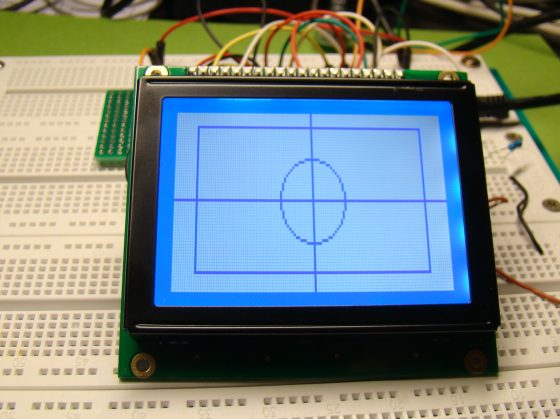
When the microcontroller runs the program, you will see 11 dotted horizontal lines displayed on the screen as shown below.

Dotted horizontal lines
Summary
In this experimental tutorial, the internal block diagram of a KS0108 based 128×64 pixel GLCD, its pin configurations, and instruction set were discussed briefly. The GLCD operation was demonstrated with a Winstar WDG0151 GLCD module interfaced to the PIC16F887 microcontroller. A very basic firmware was written in mikroC Pro for PIC to demonstrate how to activate selected pixels on the screen to draw a line. In the second part of this tutorial (will be posted soon) we will learn to use the built-in GLCD library of mikroC Pro for PIC compiler to draw more complex objects and texts on the screen.
Second part of this tutorial is here:
Lab 20: Interfacing a KS0108 based Graphics LCD (Part 2)
|
|
thanks for this solution
best regard
Sadjad
i am Using portC of PIC18F4431as data port for GLCD connections but is not working….
i need help
the code below;
// Glcd module connections
char GLCD_DataPort at PORTC;
sbit GLCD_CS1 at RD4_bit;
sbit GLCD_CS2 at RD1_bit;
sbit GLCD_RS at RD2_bit;
sbit GLCD_RW at RD3_bit;
sbit GLCD_EN at RD0_bit;
sbit GLCD_RST at RA6_bit;
sbit GLCD_CS1_Direction at TRISD4_bit;
sbit GLCD_CS2_Direction at TRISD1_bit;
sbit GLCD_RS_Direction at TRISD2_bit;
sbit GLCD_RW_Direction at TRISD3_bit;
sbit GLCD_EN_Direction at TRISD0_bit;
sbit GLCD_RST_Direction at TRISA6_bit;
// End Glcd module connections
I tried this sample and he working perfectly… thank for the tutor.
#define GLCD_Data PORTD
#define GLCD_Dir TRISD
sbit GLCD_CS1 at RB0_bit;sbit GLCD_CS2 at RB1_bit;
sbit GLCD_RS at RB2_bit;sbit GLCD_RW at RB3_bit;
sbit GLCD_RST at RB4_bit;sbit GLCD_EN at RB5_bit;
sbit GLCD_CS1_Direction at TRISB0_bit;sbit GLCD_CS2_Direction at TRISB1_bit;
sbit GLCD_RS_Direction at TRISB2_bit;sbit GLCD_RW_Direction at TRISB3_bit;
sbit GLCD_RST_Direction at TRISB4_bit;sbit GLCD_EN_Direction at TRISB5_bit;
void Enable_Pulse(){
GLCD_EN = 1;delay_us(5);GLCD_EN = 0;delay_us(5);}
void GLCD_ON(){
GLCD_CS1 = 0;GLCD_CS2 = 0;GLCD_RS = 0;GLCD_RW = 0;GLCD_Data = 0x3F;Enable_Pulse();}
void Set_Start_Line(unsigned short line){
GLCD_RS = 0;GLCD_RW = 0;GLCD_CS1 = 0;GLCD_CS2 = 0;GLCD_Data = 0xC0 | line;Enable_Pulse();}
void GOTO_COL(unsigned int x){
unsigned short Col_Data;
GLCD_RS = 0;GLCD_RW = 0;if(x63);
GLCD_CS2 = !GLCD_CS1;delay_us(1);GLCD_EN = 1;delay_us(1);
GLCD_EN = 0;delay_us(5);GLCD_EN = 1;delay_us(1);
read_data = GLCD_Data;GLCD_EN = 0;delay_us(1);GLCD_Dir = 0x00;return read_data;}
void GLCD_Clrln(unsigned short ln){
int i;
GOTO_XY(0,ln);GOTO_XY(64,ln);GLCD_CS1 = 0;
for(i=0;i<65;i++)GLCD_Write(0);}
void GLCD_CLR(){
unsigned short m;
for(m=0;m<8;m++){GLCD_Clrln(m);}}
void Draw_Point(unsigned short x,unsigned short y, unsigned short color){
unsigned short Col_Data;;
GOTO_XY(x,(y/8));
switch (color){
case 0:Col_Data = ~(1<<(y%8)) & GLCD_Read(x);break;
case 1:Col_Data = (1<<(y%8)) | GLCD_Read(x);break;}GOTO_XY(x,(y/8));GLCD_Write(Col_Data);}
void main() {
unsigned short u, v;
ANSEL = 0;ANSELH = 0;
C1ON_bit = 0;C2ON_bit = 0;TRISD = 0x00;TRISB = 0x00;PORTB = 0x00;PORTD = 0x00;
GLCD_CS1 = 1;GLCD_CS2 = 1;GLCD_RST = 1;GLCD_ON();GLCD_CLR();
Set_Start_Line(0);
do {
for(u=0; u<64; u+=6)for (v=0; v<128; v+=2)Draw_Point(v, u, 1);delay_ms(2000);GLCD_CLR();delay_ms(2000);
} while(1);}
I want to use Port C as Data Port for GLCD on PIC18F4431, but it seems not to be working……..
I need help.
here is the module connections below
// Glcd module connections
char GLCD_DataPort at PORTD;
sbit GLCD_CS1 at RB0_bit;
sbit GLCD_CS2 at RB1_bit;
sbit GLCD_RS at RB2_bit;
sbit GLCD_RW at RB3_bit;
sbit GLCD_EN at RB4_bit;
sbit GLCD_RST at RB5_bit;
sbit GLCD_CS1_Direction at TRISB0_bit;
sbit GLCD_CS2_Direction at TRISB1_bit;
sbit GLCD_RS_Direction at TRISB2_bit;
sbit GLCD_RW_Direction at TRISB3_bit;
sbit GLCD_EN_Direction at TRISB4_bit;
sbit GLCD_RST_Direction at TRISB5_bit;
// End Glcd module connections
Not working…
I programmed this into a project exactly as you described, programmed the chip and it show nothing on the LCD! I’ve worked on it for a few days without results.
Thanks for the program which doesn’t work for me.
Jim Darcy
Hi I have a problem with TG12864B-02WA0 display…. I want to use this LCD with ATMEGA16A-PU But when I programming this display don’t working. I did’t find any example project so can you share any library documantary for atmel
Hi everybody;
In the description it says “An external potentiometer (usually 10 K) is connected between Vcc and VEE pins to set the LCD working voltage (contrast) at Vo pin”; however in the circuit diagram, the potentiometer had been connected between Gnd and VEE.
I am a little bit confused. Have I miss something?;
last night I destroyed one WG12864A because of lack of experience and my terrible mistake in Vee and Vo.
Thanx.
Ahmet,
Since Vee is a negative voltage, connect the potentiometer between VCC and VEE to achieve a larger dynamic range for the contrast adjustment voltage.
kindly let me know which graphical lcd have you used i mean how can i choose it in proteus 8?
I am transfering this code for STM32 microcontroller,
in function: unsigned short GLCD_Read(unsigned short column)
there is : GLCD_CS1 = (column>63);
I dont know what is assigned to GLCD_CS1
would you please make this command clear?
I have a doubt that how to display an image in GLCD using ARM.I can get 25% of image as output.
Could anyone help me interface an S6B0108 based 128×64 GLCD with an ArduinoMega2560?
plz help I am using glcd 164×28 of Topway LM12864DDY
http://www.topwaydisplay.com/Pub/Manual/LM12864DDY-Manual-Rev0.1.pdf
I am using CCS C Compiler & interfacing with pic16f877a
I have used many codes but could not get results data is not shown on LCD here is my code plz help
#include
#fuses HS,NOWDT,NOPROTECT,NOLVP
#use delay(clock=20000000)
#include “HDM64GS12.c”
#include
#include
void main() {
char voltText[] = “Volts”;// warning[] = “Warning”;
delay_ms(100);
glcd_init(ON);
glcd_fillScreen(OFF);
while(true)
{
glcd_rect(1, 5, 126, 15, NO, ON);
glcd_text57(70, 18, voltText, 1, ON);
glcd_circle(30, 47, 10, NO, ON);
}
}
The diagram from Winstar says that the POT should be connected between VDD and VEE. You have it as VSS and VEE.
hi
i want to know how can i do this project with Codevision software
it needs C language for programing
thanks
I am writing a program which can take the analogue voltage reading and use adc to convert this signal into digital signal and display In terms of digital values. Initially I was using a digital lcd and displayed the above mentioned data on lcd. Now I need a program which can display the data in the form of a dial (gauge) on GLCD with a needle showing the change in voltage.
I am using
1. PIC – C compiler
2. 18F452 micro controller
3. HDM64GS12 GLCD with a KS0108 display controller. The HDM64GS12 is 128 by 64 pixels GLCD
4. I have driver file “HDM64GS12.c”. This file contains drivers for using a Hantronix HDM64GS12 .
5. I also have a graphics file named ”graphics.c”. It contains functions to draw lines, rectangles, bars, circles and text to a display
I want to know the sequence of instructions that needs to carried out to initialize Glcd
it’s written above in that code. “GLCD_ON()”
Only thing that’s peculiar is… every glcd i’ve used…CS1 and 2 should be set during initializing…
I believe there’s errors in this code, as identified in other comments…clearline funciton needs to be modified to the code in the comment below
Good afternoon 😀 I nedd your help. How I can plot an analog signal using the PIC16F887 and this GLCD? ¡Pleeaaase!
thanks..
BTW, this function should look like this:
void GLCD_Clrln(unsigned short ln)
{
int i;
GOTO_XY(0,ln);
GLCD_CS1 = 0;
GLCD_CS2 = 1;
for(i=0;i<65;i++)
GLCD_Write(0);
GOTO_XY(64,ln);
GLCD_CS1 = 1;
GLCD_CS2 = 0;
for (i=0; i<65; i++)
GLCD_Write(0);
}
Good tutorial! Thanks!
THANK YOU ABOUT THIS IMPOTRANT INFORMATION >>>>
I WILL BE THANKFULL IF YOU SUPPLY ME WITH TUTORIAL ABOUT INTERFACE AVR ATMEL WITH 64128Q DISPLAYTECH GRAPHIC LCD….ESPECIALLY IF ITS BY ASSEMBLY LANGUAGE>>.
you are best
thank you
Never mind .. looks like I’d forgotten to GLCD_init for the mikroC libraries 🙂
I’m finding that the mikroC built in graphic libraries don’t get along with the code here. I’m sure it’s grabbing pointers to things that the mikroC libraries need .. any thoughts on how to get them to co-exist ? I need the speed of the “GLCD_Write” function and the versatility of the mikroC libraries both.
Thanks !
Pingback: tutorials for Graphic LCD
Pingback: Reviewing the iCA05 Graphic LCD development kit from iCircuit Technologies » Geko Geek
Pingback: Electronics-Lab.com Blog » Blog Archive » Interfacing a KS0108 based Graphics LCD (Part 2)
Pingback: Interfacing a KS0108 based Graphics LCD (Part 2) » Geko Geek
i think in microC there is a built in library for working with KS108 displays ?
Alexander,
Yes it does.
Hi, I’m trying to display this GLCD. I have copied the source code.
The different is, I don’t have 10K variable, so I use 1K variable. I measure voltage at Vee is -6V. Is that, because of this my GLCD dosn’t display anythig?
Shahrul,
Vee is negative because of the negative voltage generator built inside the module. It is normal. Try adjusting the LCD contrast by varying the potentiometer. Make sure you have connected everything correctly.