Lab 6: Seven segment display
|
|
Introduction
Seven segment LED displays are often found in clock radios, VCRs, microwave ovens, toys and many other household items. They are primarily used to display decimal numbers but they can also display a few alphabets and other characters. This experiment describes interfacing a seven segment LED display to a PIC16F688 microcontroller. You will make a hexadecimal counter that counts from 0 (00h) to 15 (0Fh) and display the value on the seven segment LED display.
Required Theory
A seven segment LED display is an special arrangement of 7 LED elements to form a rectangular shape using two vertical segments on each side with one horizontal segment on the top, middle, and bottom. By individually turning the segments on or off, numbers from 0 to 9 and some letters can be displayed. Seven segment displays sometime also have an eighth segment to display the decimal point. Therefore, a seven-segment display will require seven outputs from the microcontroller to display a number, and one more output if the decimal point is to be displayed too.
The segments are marked with non-capital letters: a, b, c, d, e, f, g and dp, where dp is the decimal point. The 8 LEDs inside the display can be arranged with a common cathode or common anode configuration. With a common cathode display, the cathodes of all the segment LEDs are tied together and this common point must be connected to the ground. A required LED segment is then turned on by applying a logic 1 to its anode. In common anode displays, all the anodes are tied together and the common anode is connected to the supply voltage Vcc. Individual segments are turned on by applying logic 0 to their cathodes.
When more than one seven segment display is used, a multiplexing technique is used to minimize the required number of microcontroller pins. We will discuss about that technique later.
In this experiment, a LT543 model common cathode seven segment display is used. The segment LEDs glow red when turned on. The module has 10 pins whose configuration is shown below.

All the cathodes are connected together and the common cathode point is available at pins 3 and 8. The anodes are driven through a microcontroller’s I/O pins with current limiting resistors in series. Displaying a number requires turning on and off the proper segment LEDs. For example, to display a number 7, only segments a, b, and c should be turned on.
Circuit Diagram
The circuit diagram for connecting a common cathode seven segment LED display to the PIC16F688 microcontroller port is shown below. The microcontroller I/O pins source the current required for the segment LEDs. The current limiting resistors connected in series between the microcontroller pina and segment LEDs are 330 ? each. Segments a-f are driven through RC0-RC5, and the segment g is driven by RA2. The decimal point is not used. Please check the manufacturer’s datasheet to identify the segment pins of your seven segment display module.

Circuit diagram for seven segment display interface

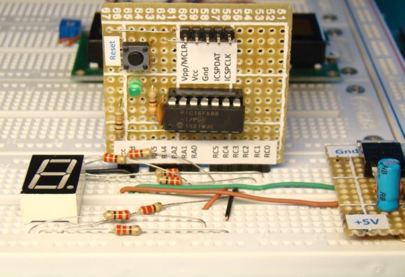
Circuit setup on the breadboard
Software
The segment LEDs are driven through PORTC and PORTA, so they are defined as digital outputs. Any comparator functions in these pins must be disabled too. The program counts from 0 through 15, with 1 sec interval, and rolls over to 0 again. The count values are shown on the seven segment display as 0, 1, 2, 3, 4, 5, 6, 7, 8, 9, A, B, C, D, E, and F. Compile the following program with the MikroC Pro for PIC compiler from MikroElektronika and load the HEX file into the PIC16F688 microcontroller. Read the first lab session, Lab 1: Flashing an LED, for the clock and configuration bit settings of the microcontroller.
/*Lab 6: Seven segment displayCopyright @ Rajendra BhattNovember 13, 2010*/// Define seven segment connectionssbit seg_a at RC0_bit;sbit seg_b at RC1_bit;sbit seg_c at RC2_bit;sbit seg_d at RC3_bit;sbit seg_e at RC4_bit;sbit seg_f at RC5_bit;sbit seg_g at RA0_bit;unsigned short count=0;void main() {ANSEL = 0b00000000; //All I/O pins are configured as digitalCMCON0 = 0x07 ; // Disbale comparatorsTRISC = 0b00000000; // PORTC All OutputsTRISA = 0b00001000; // PORTA All Outputs, Except RA3do {switch (count) {case 0 : seg_a=1; seg_b=1; seg_c=1;seg_d=1; seg_e=1; seg_f=1; seg_g=0;break;case 1 : seg_a=0; seg_b=1; seg_c=1; seg_d=0;seg_e=0; seg_f=0; seg_g=0;break;case 2 : seg_a=1; seg_b=1; seg_c=0; seg_d=1;seg_e=1; seg_f=0; seg_g=1;break;case 3 : seg_a=1; seg_b=1; seg_c=1; seg_d=1;seg_e=0; seg_f=0; seg_g=1;break;case 4 : seg_a=0; seg_b=1; seg_c=1; seg_d=0;seg_e=0; seg_f=1; seg_g=1;break;case 5 : seg_a=1; seg_b=0; seg_c=1; seg_d=1;seg_e=0; seg_f=1; seg_g=1;break;case 6 : seg_a=1; seg_b=0; seg_c=1; seg_d=1;seg_e=1; seg_f=1; seg_g=1;break;case 7 : seg_a=1; seg_b=1; seg_c=1; seg_d=0;seg_e=0; seg_f=0; seg_g=0;break;case 8 : seg_a=1; seg_b=1; seg_c=1; seg_d=1;seg_e=1; seg_f=1; seg_g=1;break;case 9 : seg_a=1; seg_b=1; seg_c=1; seg_d=0;seg_e=0; seg_f=1; seg_g=1;break;case 10 : seg_a=1; seg_b=1; seg_c=1; seg_d=0;seg_e=1; seg_f=1; seg_g=1;break;case 11 : seg_a=0; seg_b=0; seg_c=1; seg_d=1;seg_e=1; seg_f=1; seg_g=1;break;case 12 : seg_a=1; seg_b=0; seg_c=0; seg_d=1;seg_e=1; seg_f=1; seg_g=0;break;case 13 : seg_a=0; seg_b=1; seg_c=1; seg_d=1;seg_e=1; seg_f=0; seg_g=1;break;case 14 : seg_a=1; seg_b=0; seg_c=0; seg_d=1;seg_e=1; seg_f=1; seg_g=1;break;case 15 : seg_a=1; seg_b=0; seg_c=0; seg_d=0;seg_e=1; seg_f=1; seg_g=1;break;} //case endcount ++;if(count ==16) count =0;Delay_ms(1000); // Wait for 1 sec before updating the display} while(1); // Infinite Loop}
Output
After the program is loaded into the microcontroller, turn the power on and see the hex counter counting from 0 to F.


|
|
Pingback: [PIC] i want to help in this simple circuit of 7 segment
how to write prject for seven segment display
It would be nice to have more pic theory Raj
thank you!
marC:)
good morning
please can you help me to build my own seven segment clock by using 3 button;
*one for hours
*next for minuts
*next for seconds
please can you help me to make a seven clock that we can use 3 botton
_hour
_minut
_seconde
wow this is very impacting. i really want to commend u guys. please i want to request if the code can be written using ccs. i will really appreciate cos i’m working on it now for my project
Pingback: Dinesh Labs Limited « PowerControllers
Great article! I noticed a small discrepancy between the circuit diagram and the code. Your circuit and the description say segment g is driven by RA2. However the code and the provided Hex file actually use RA0.
Thanks for all the information on this site! Looking forward to the discussion on multiplexing.
You are right, Matt. I have corrected it in the circuit diagram. Thank you.
Instead of using a very long case statement, it is much simpler to use an array.
char[] SSD = { 11111110, 01100000, ……}
segments = SSD[n]; //segments are the I/O ports of the SSD
Keep up the good work!
You are extremely productive! And i like the way you document your articles. It will be featured in pcbheaven.com today