PIC12F microcontroller project board
|
|
The 12F series of PIC microcontrollers are handy little 8-pin devices designed for small embedded applications that do not require too many I/O resources, and where small size is advantageous. These applications include a wide range of everyday products such as hair dryers, electric toothbrushes, rice cookers, vacuum cleaners, coffee makers, and blenders. Despite their small size, the PIC12F series microcontrollers offer interesting features including wide operating voltage, internal programmable oscillator, 4 channels of 10-bit ADC, on-board EEPROM memory, on-chip voltage reference, multiple communication peripherals (UART, SPI, and I2C), PWM, and more. The following project board is designed for fast and easy development of standalone applications using PIC12F microcontrollers. It features on-board regulated +5V power supply, header connectors to access I/O pins, ICSP header for programming, a reset circuit, and small prototyping area for placing additional components.

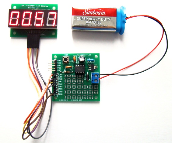
PIC12F development board driving a serial seven segment LED display
The picture below shows a closer view of the features on board.

On-board features
- Two-pin terminal block for DC input (6-12V DC)
- AMS1117-5.0V regulator
- PIC12F microcontroller on a DIP IC socket
- Tact switch connected to RA3 I/O pin, which is input only. It can be used to reset the microcontroller if MCLR is enabled. Otherwise, it can be used as an user input switch.
- Header connector for ICSP programming using chipKIT2/3.
- Headers to access I/O pins and power supply pins (Vcc = +5V). Note that RA5 has been mislabeled as RP5 on silkscreen.
- Small prototyping area for connecting additional circuit. The regulated +5V power supply for the additional circuit can be derived from the Vcc header pins.
Important: The RA0-RA5 names are used for I/O pins of the PIC12F micrcontrollers in the enhanced mid-range family (PIC12F1822, PIC12F1840, etc). The corresponding I/O pins for the old ones (PIC12F629, PIC12F675, PIC12F683, etc) are named as GP0-GP5, and have the same pin configurations. Therefore, this board can be used for both.
Test program
The following program is written in mikroC Pro for PIC compiler to illustrate the interfacing of the 4-digit serial seven segment LED display module with the PIC12F development board. The microcontroller used on the board is PIC12F683. The GP0, GP1, and GP2 pins of the PIC12F683 drives the CS, MOSI, and CLK pins, respectively, of the 7-segment display module to create a 4-digit up-counter. The counter counts from 0000 to 9999 and then reset to zero and start again.
// Define Soft-SPI connections
#define CS_Pin       GP0_bit
#define MOSI_Pin     GP1_bit
#define CLK_Pin      GP2_bit

void SPI_Write_Byte(unsigned short num){
 unsigned short t, Mask, Flag;
 CLK_Pin = 0;
 Mask = 128;
 for (t=0; t<8; t++){
  Flag = num & Mask;
  if(Flag == 0) MOSI_Pin = 0;
  else MOSI_Pin = 1;
  CLK_Pin = 1;
  CLK_Pin = 0;
  Mask = Mask >> 1;
 }
}

void MAX7219_INIT() {
  // Disable Shutdown mode
  CS_Pin = 0;              // CS pin is pulled LOW
  SPI_Write_Byte(0x0C);    // Select Shutdown register
  SPI_Write_Byte(0x01);    // Set D0 bit to return to normal operation
  CS_Pin = 1;              // CS pin is pulled HIGH

  // Set BCD decode mode for digits DIG0-DIG3
  CS_Pin = 0;              // CS pin is pulled LOW
  SPI_Write_Byte(0x09);    // Select Decode Mode register
  SPI_Write_Byte(0x0F);    // Select BCD mode for digits DIG0-DIG3
  CS_Pin = 1;              // CS pin is pulled HIGH

  // Set display brighness
  CS_Pin = 0;              // CS pin is pulled LOW
  SPI_Write_Byte(0x0A);    // Select Intensity register
  SPI_Write_Byte(0x0F);    // Set maximum brightness
  CS_Pin = 1;              // CS pin is pulled HIGH

   // Set display refresh
  CS_Pin = 0;              // CS pin is pulled LOW
  SPI_Write_Byte(0x0B);    // Select Scan-Limit register
  SPI_Write_Byte(0x03);    // Select digits DIG0-DIG3
  CS_Pin = 1;              // CS pin is pulled HIGH

 // Enable Display-Test
  CS_Pin = 0;              // CS pin is pulled LOW
  SPI_Write_Byte(0x0F);    // Select Display-Test register
  SPI_Write_Byte(0x01);    // Enable Display-Test
  CS_Pin = 1;              // CS pin is pulled HIGH

  Delay_ms(1000);
 // Disable Display-Test
  CS_Pin = 0;              // CS pin is pulled LOW
  SPI_Write_Byte(0x0F);    // Select Display-Test register
  SPI_Write_Byte(0x00);    // Disable Display-Test
  CS_Pin = 1;              // CS pin is pulled HIGH

}

 void Display_Counter(unsigned int j){
  CS_Pin = 0;                    // CS pin is pulled LOW
  SPI_Write_Byte(4);             // Send thousands digit
  SPI_Write_Byte((j/1000)%10);
  CS_Pin = 1;                    // CS pin is pulled HIGH

  CS_Pin = 0;                    // CS pin is pulled LOW
  SPI_Write_Byte(3);             // Send hundreds digit
  SPI_Write_Byte((j/100)%10);
  CS_Pin = 1;                    // CS pin is pulled HIGH

  CS_Pin = 0;                    // CS pin is pulled LOW
  SPI_Write_Byte(2);             // Send tens digit
  SPI_Write_Byte((j/10)%10);
  CS_Pin = 1;                    // CS pin is pulled HIGH

  CS_Pin = 0;                    // CS pin is pulled LOW
  SPI_Write_Byte(1);             // Send ones digit
  SPI_Write_Byte(j%10);
  CS_Pin = 1;                    // CS pin is pulled HIGH
 }

unsigned short i;
unsigned int counter = 0;

void main() {
  TRISIO=0b00001000;        // GP3 is input only
  CMCON0 = 0x07;
  ANSEL = 0x00;
  MAX7219_INIT();           // Initialize  MAX7219
  do{
   for (counter=0; counter<10000; counter++) {
    Display_Counter(counter);
    Delay_ms(1000);
   }
  }while(1);
}
Wondering what you can do with this board? If you search online you will find tons of cool projects done with PIC12F microcontrollers. Here’s a list of few of them.
- A beginner’s data logger with serial interface
- 0-20V digital voltmeter
- Playing a song tune with PIC12F683
- Ultrasonic sound detector
- Metal detector
- PAL video superimposer
- Laser projector
- A super simple IR remote
- Thermometer with Nokia 3310 LCD
- Pong video game
- Mini servo controller
- Temperature sensing mug
- IR light dimmer
There are many more!
Right now I have got 12 PCBs of this board. I will keep five for myself, and will give out the rest. Let me know if you need one. It will be $7.99 for one PCB including free shipping within the continental United States. You will need following parts to assemble the board.
- Four capacitors: C1, C2, C4 = 0.1uF ceramic, and C3 = 10uF-100uF electrolytic.
- One resistor, R1 = 10K.
- One 2-pin tact switch, 6mm x 6mm.
- One AMS1117 TO-223 regulator.
- One 1N4004 1.0A diode.
- One 2-pin terminal block (5mm spacing) for DC input.
- One 8-pin DIP socket.
- PIC12F microcontroller of your choice (PIC12F683, PIC12F675, PIC12F1822, PIC12F1840, etc).
- Header connectors for ICSP and I/O pins.

PCB size is 1.95 inches x 1.95 inches

Bottom side of PCB board
Note: The pin number 1 of the PIC12F microcontroller is identified by the small square soldering pad in its footprint on the PCB.

Assembled board
Update: This board has gone through some revisions. Please visit the following link for a revised version of this board.
http://embedded-lab.com/blog/?p=5619
|
|
Can you e-mail me the schematic? I don’t seem to see it on this page or a link to it. I would really appreciate it
Nevermind I found it. Thank you. Keep up the awesome work.
I need the entire circuit diagram of the board.
Hi! I would like to make the PIC12F breadboard. Can you send me the schematics?
Thank you!
JSV
I don’t have it now. But I will post it soon.
Did you ever get around finishing this schematic? I would like to build this on a bread board, thanks!
Randy,
I sent you the circuit diagram to your email id rasyoung@indiana.edu but it says it can’t be reached.
Pingback: La semana en links (26/06/2012) | Automatismos Mar del Plata
Would you please include a picture of the bottom and a schematic?
Thanks
I have included the picture of the bottom side of PCB. I will post the schematic soon after a small revision.