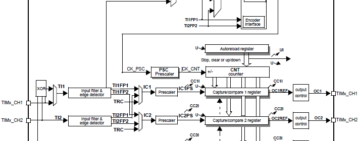
STM32 Timers
|
|
Multiple Timer Interrupt Example
This example is just like the previous one except this time the code is written with my SPL functions and two timers are running simultaneously with different clock frequencies. LEDs connected to GPIOC 6 and 7 pins flash to show the update rates of these timers. An advance and a GP timer are used in the demo.
#include "TIM_common.h"
#include "TIM3.h"
#include "TIM8.h"
#include "GPIO.h"
void setup();
void GPIO_init();
void Timer3_init();
void Timer8_init();
void TIM3_ISR()
iv IVT_INT_TIM3
ics ICS_AUTO
{
TIM3_SR = 0;
GPIOC_pin_toggle(6);
}
void TIM8_ISR()
iv IVT_INT_TIM8_UP
ics ICS_AUTO
{
TIM8_SR = 0;
GPIOC_pin_toggle(7);
}
void main()
{
setup();
while(1)
{
};
}
void setup()
{
GPIO_init();
Timer3_init();
Timer8_init();
}
void GPIO_init()
{
enable_GPIOC(true);
setup_GPIOC(6, (GPIO_PP_output | output_mode_medium_speed));
setup_GPIOC(7, (GPIO_PP_output | output_mode_medium_speed));
}
void Timer3_init()
{
enable_TIM3(true);
enable_TIM3_counter(false);
TIM3_PSC = 575;
TIM3_ARR = 62499;
set_TIM3_counting_direction(down_counting);
NVIC_IntEnable(IVT_INT_TIM3);
EnableInterrupts();
enable_TIM3_update_interrupt(true);
enable_TIM3_counter(true);
}
void Timer8_init()
{
enable_TIM8(true);
enable_TIM8_counter(false);
TIM8_PSC = 575;
TIM8_ARR = 62499;
set_TIM8_counting_direction(up_counting);
NVIC_IntEnable(IVT_INT_TIM8_UP);
EnableInterrupts();
enable_TIM8_update_interrupt(true);
enable_TIM8_counter(true);
}
Demo video link: https://www.youtube.com/watch?v=jyPUu5JqZyU.
External Clock Drive/Counter Example
In the beginning I stated that timers can be driven with external clock sources. STM32 timers can be driven with three types of external sources. We can use this facility to count pulses coming from a sensor like a Hall position sensor. We can also cascade several such timers to form a high precision timer. In this example, we will see how this is done.
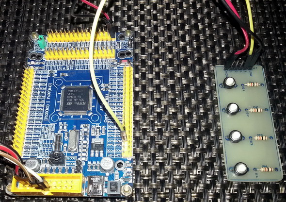
The following hardware setup is used.
Please refer to the code. Note GPIOA 0 pin is used as the input of the external clock source. Here I connected a button to stimulate the external clock source. Note that the AFIO block has been enabled but no pin remapping is used. I avoided pin remapping to keep things simple although pin remapping is not hard. The following code sets up external clock properties.
set_TIM2_clock_division(clock_division_tCK_INT);
set_TIM2_CC1_selection(CC1_input_IC1_on_TI1);
set_TIM2_CC1_state_and_polarity(enable, rising_edge);
set_TIM2_trigger_source(TI1_edge_detector);
set_TIM2_slave_selection(external_clock_mode_1);
As you can see the external clock source will only be sensed during rising edge transitions. Its input channel enabled and selected.
The rest of the code in the timer setup simply state how much to count before invoking an interrupt and should there be any prescaling for the incoming signal. This code makes my STM32 board sense two rising edges before invoking an interrupt and toggling a LED connected to GPIOC 6 pin. Pretty simple.
#include "TIM_common.h"
#include "TIM2.h"
#include "AFIO.h"
#include "GPIO.h"
void setup();
void setup_IO();
void setup_TIM2();
void TIM2_ISR()
iv IVT_INT_TIM2
ics ICS_AUTO
{
TIM2_SR = 0;
GPIOC_pin_toggle(6);
}
void main()
{
setup();
while(1);
}
void setup()
{
setup_IO();
setup_TIM2();
}
void setup_IO()
{
AFIO_enable(true);
AFIO_remap(TIM2_not_remapped);
enable_GPIOA(true);
setup_GPIOA(0, input_without_pull_resistors);
enable_GPIOC(true);
setup_GPIOC(6, (GPIO_PP_output | output_mode_high_speed));
GPIOC_pin_high(6);
}
void setup_TIM2()
{
enable_TIM2(true);
enable_TIM2_counter(false);
TIM2_ARR = 0x0002;
TIM2_PSC = 0x0000;
set_TIM2_counting_direction(up_counting);
set_TIM2_clock_division(clock_division_tCK_INT);
set_TIM2_CC1_selection(CC1_input_IC1_on_TI1);
set_TIM2_CC1_state_and_polarity(enable, rising_edge);
set_TIM2_trigger_source(TI1_edge_detector);
set_TIM2_slave_selection(external_clock_mode_1);
enable_TIM2_update_interrupt(true);
NVIC_IntEnable(IVT_INT_TIM2);
EnableInterrupts();
enable_TIM2_counter(true);
}
Demo video link: https://www.youtube.com/watch?v=jCVWCoJeqec.
|
|
well done sir
How to set the PWM with Center aligned mode ?
Read this app note: http://www.st.com/web/en/resource/technical/document/application_note/DM00042534.pdf
Thanks,
Now need the sample code to change the CMS bits different from ’00’
Great tutorials! Best I’ve found so far.
Thanks…. 🙂
first of all i like to say a million thanks for this tutorial and i have been waiting for this
tutorial i am your biggest fan in stm32 programming for there is little information about it on the web you’ve motivated me to keep having interest in on knowing about the 32bit micros
Thanks…. People like you keeps me going…. 🙂
Pingback: STM32 Timers - Arduino collector blog