STM32 Timers
|
|
Pulse Width Measurement Example
This is another useful application of input capture mode. Using two I/O pins simplify coding. One pin is set to capture rising edges while the other is configured to capture falling edges. Just like the previous example we need to detect the time difference between two successive capture events. Technically this example is an extension of the previous example.
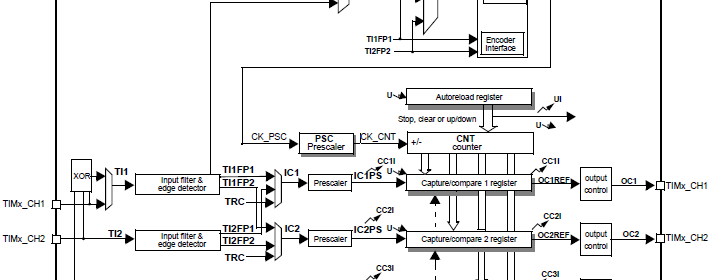
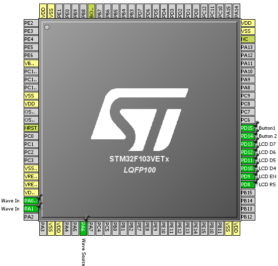
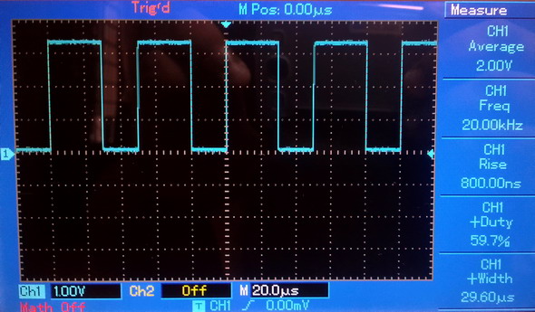
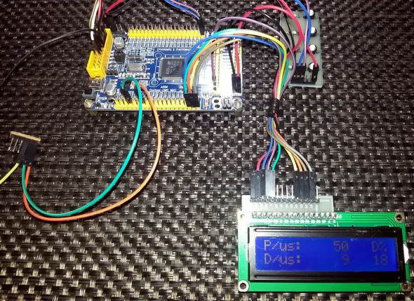
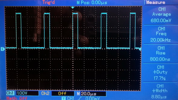
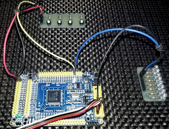
In this example, timer 3 is used as a PWM generator. The PWM waveform will have a frequency of 20 kHz. Two input capture channels are used to detect the two different edges of this PWM. The time difference between a rising edge and a falling edge gives the mark time and the time difference between two rising/falling edges gives the time period of the PWM waveform. Two push buttons connected to GPIOD pins 14 and 15 are used to change the duty cycle of the PWM waveform.
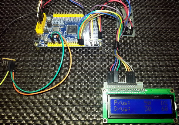
The hardware setup looks like this:
 #include “TIM_common.h”
#include "TIM2.h"
#include "TIM3.h"
#include "AFIO.h"
#include "GPIO.h"
sbit LCD_RS at GPIOD_ODR.B8;
sbit LCD_EN at GPIOD_ODR.B9;
sbit LCD_D4 at GPIOD_ODR.B10;
sbit LCD_D5 at GPIOD_ODR.B11;
sbit LCD_D6 at GPIOD_ODR.B12;
sbit LCD_D7 at GPIOD_ODR.B13;
unsigned int second_rise = 0;
unsigned int start_time = 0;
unsigned int end_time = 0;
unsigned int d = 0;
unsigned int t = 0;
void setup();
void setup_IO();
void setup_TIM2();
void setup_TIM3();
void TIM2_ISR()
iv IVT_INT_TIM2
ics ICS_AUTO
{
if(TIM2_SRbits.CC1IF == 1)
{
TIM2_SRbits.CC1IF = 0;
start_time = TIM2_CCR1;
if(start_time > second_rise)
{
t = (start_time - second_rise);
}
else
{
t = (0xFFFF - start_time + second_rise);
}
}
if(TIM2_SRbits.CC2IF == 1)
{
TIM2_SRbits.CC2IF = 0;
end_time = TIM2_CCR2;
if(start_time < end_time)
{
d = (end_time - start_time);
}
else
{
d = (0xFFFF - end_time + start_time);
}
}
second_rise = start_time;
}
void main()
{
unsigned char duty_cycle = 0;
signed int pwm = 100;
char txt[15];
setup();
while(1)
{
if(get_GPIOD_pin_state(14))
{
pwm += 50;
}
if(pwm >= 3550)
{
pwm = 3550;
}
if(get_GPIOD_pin_state(15))
{
pwm -= 50;
}
if(pwm <= 50)
{
pwm = 50;
}
TIM3_CCR1 = pwm;
duty_cycle = (((float)d / (float)t) * 100);
lcd_out(1, 7, " ");
WordToStr(t, txt);
lcd_out(1, 7, txt);
lcd_out(2, 7, " ");
WordToStr(d, txt);
lcd_out(2, 7, txt);
ByteToStr(duty_cycle, txt);
lcd_out(2, 14, txt);
delay_ms(600);
};
}
void setup()
{
setup_IO();
setup_TIM2();
setup_TIM3();
Lcd_Init();
Lcd_Cmd(_LCD_CLEAR);
Lcd_Cmd(_LCD_CURSOR_OFF);
lcd_out(1, 1, "P/us:");
lcd_out(2, 1, "D/us:");
lcd_out(1, 15, "D%");
}
void setup_IO()
{
AFIO_enable(true);
AFIO_remap(TIM2_not_remapped);
enable_GPIOA(true);
setup_GPIOA(0, digital_input);
enable_pull_down_GPIOA(0);
setup_GPIOA(1, digital_input);
enable_pull_down_GPIOA(1);
setup_GPIOA(6, (AFIO_PP_output | output_mode_high_speed));
enable_GPIOD(true);
setup_GPIOD(8, (GPIO_PP_output | output_mode_low_speed));
setup_GPIOD(9, (GPIO_PP_output | output_mode_low_speed));
setup_GPIOD(10, (GPIO_PP_output | output_mode_low_speed));
setup_GPIOD(11, (GPIO_PP_output | output_mode_low_speed));
setup_GPIOD(12, (GPIO_PP_output | output_mode_low_speed));
setup_GPIOD(13, (GPIO_PP_output | output_mode_low_speed));
setup_GPIOD(14, input_without_pull_resistors);
setup_GPIOD(15, input_without_pull_resistors);
}
void setup_TIM2()
{
enable_TIM2(true);
enable_TIM2_counter(false);
TIM2_ARR = 0xFFFF;
TIM2_PSC = 71;
set_TIM2_counting_direction(up_counting);
set_TIM2_clock_division(clock_division_tCK_INT);
set_TIM2_CC1_selection(CC1_input_IC1_on_TI1);
set_TIM2_CC2_selection(CC2_input_IC2_on_TI1);
set_TIM2_CC1_state_and_polarity(enable, rising_edge);
set_TIM2_CC2_state_and_polarity(enable, falling_edge);
set_TIM2_IC1_input_prescalar(0);
set_TIM2_IC2_input_prescalar(0);
set_TIM2_IC1_filter(0);
set_TIM2_IC2_filter(0);
enable_TIM2_CC1_interrupt(true);
enable_TIM2_CC2_interrupt(true);
NVIC_IntEnable(IVT_INT_TIM2);
EnableInterrupts();
enable_TIM2_counter(true);
}
void setup_TIM3()
{
enable_TIM3(true);
enable_TIM3_counter(false);
set_TIM3_counting_direction(up_counting);
TIM3_ARR = 3599;
TIM3_PSC = 0;
set_TIM3_OC1_compare_mode(PWM_mode_2);
set_TIM3_CC1_state_and_polarity(enable, active_low);
enable_TIM3_counter(true);
}
Demo video link: https://www.youtube.com/watch?v=BJI5K0yBm6s.
One Pulse Mode Example
One pulse mode is a combination of both input capture and output compare modes. In this mode a timer behaves like a monostable multivibrator (A.K.A one shot timer). It will fire a pulse of a given width and then go to idle state. This is another feature that is uncommon to most other micros.
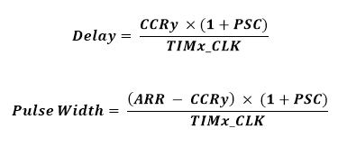
There are two timings to consider when using one pulse mode. First is the delay after which the pulse will be generated and second is the pulse width. These are calculated as follows:
The following code sets up timer 2 for one pulse mode:
set_TIM2_counting_direction(up_counting);
set_TIM2_clock_division(clock_division_tCK_INT);
set_TIM2_CC1_selection(CC1_input_IC1_on_TI1);
set_TIM2_CC1_state_and_polarity(enable, rising_edge);
set_TIM2_CC2_selection(CC2_output);
set_TIM2_CC2_state_and_polarity(enable, active_high);
set_TIM2_OC2_compare_mode(PWM_mode_2);
set_TIM2_trigger_source(Filtered_Timer_Input_1);
set_TIM2_slave_selection(trigger_mode);
TIM2_ARR = 60000;
TIM2_PSC = 0x0000;
TIM2_CCR2 = 20;
The code configures an input capture c and an output compare channel. It sets up their properties. The different thing in this code from the others is the slave selection and the trigger source selection. Trigger mode needs to be selected for one pulse mode.
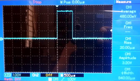
Note the values of ARR, PSC and CCR2 registers. With these values we will get a pulse of 833µs after a delay of about 280ns.
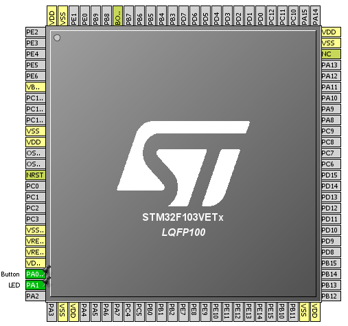
In my example I used a button to trigger the timer and an LED to show the output. When the button is pressed, the LED will briefly light and then extinguish, showing one shot characteristics.
The hardware setup for this example is like this:
#include "TIM_common.h"
#include "TIM2.h"
#include "AFIO.h"
#include "GPIO.h"
void setup();
void setup_IO();
void setup_TIM2();
void main()
{
setup();
while(1)
{
};
}
void setup()
{
setup_IO();
setup_TIM2();
}
void setup_IO()
{
AFIO_enable(true);
AFIO_remap(TIM2_not_remapped);
enable_GPIOA(true);
setup_GPIOA(0, digital_input);
enable_pull_down_GPIOA(0);
setup_GPIOA(1, (AFIO_PP_output | output_mode_high_speed));
}
void setup_TIM2()
{
enable_TIM2(true);
enable_TIM2_counter(false);
set_TIM2_counting_direction(up_counting);
set_TIM2_clock_division(clock_division_tCK_INT);
set_TIM2_CC1_selection(CC1_input_IC1_on_TI1);
set_TIM2_CC1_state_and_polarity(enable, rising_edge);
set_TIM2_CC2_selection(CC2_output);
set_TIM2_CC2_state_and_polarity(enable, active_high);
set_TIM2_OC2_compare_mode(PWM_mode_2);
set_TIM2_trigger_source(Filtered_Timer_Input_1);
set_TIM2_slave_selection(trigger_mode);
TIM2_ARR = 60000;
TIM2_PSC = 0x0000;
TIM2_CCR2 = 20;
enable_TIM2_counter(true);
}
Demo video link: https://www.youtube.com/watch?v=-qctr7AVrrI.
Epilogue
Oh that was too much for one post I guess. Nearly one month of hard work and continuous studies compiled here. I believe it is my longest post so far. Previously the post on STM32 ADC was the longest. I tried my best to give the most out of STM32 timers. A total of nine examples I suppose covered most of the STM32 timer stuffs one can desire. DMA-based operations were skipped for future just as like other posts. I would suggest readers to read the STM32 Timer Overview application note (AN4013) from ST instead of going through the reference manuals:
http://www.st.com/web/en/resource/technical/document/application_note/DM00042534.pdf
This app note described timers pretty much simply than reference manuals. I’m not suggesting to avoid the reference manuals. They’ll be needed for register overviews and other tasks.
References:
- STM32 Reference Manual RM0008.
- STM32 Timer Overview AN4013.
Happy coding.
Author: Shawon M. Shahryiar
Repository: https://github.com/sshahryiar/STM32-Tutorials
Author: Shawon M. Shahryiar
https://www.youtube.com/c/sshahryiar
|
|
well done sir
How to set the PWM with Center aligned mode ?
Read this app note: http://www.st.com/web/en/resource/technical/document/application_note/DM00042534.pdf
Thanks,
Now need the sample code to change the CMS bits different from ’00’
Great tutorials! Best I’ve found so far.
Thanks…. 🙂
first of all i like to say a million thanks for this tutorial and i have been waiting for this
tutorial i am your biggest fan in stm32 programming for there is little information about it on the web you’ve motivated me to keep having interest in on knowing about the 32bit micros
Thanks…. People like you keeps me going…. 🙂
Pingback: STM32 Timers - Arduino collector blog