STM32 Timers
|
|
Pulse Width Modulation (PWM)
Pulse Width Modulation (PWM) is another feature that is common in most modern MCUs. With PWM outputs, we can generate waveforms as per our need and so often it is said that PWMs mimic analogue outputs. In reality PWMs don’t output continuous analogue voltages like Digital-Analogue Converters but rather output variable width pulses that have average values. A low-pass RC filter can be used to obtain continuous output voltages while blocking high frequency PWM waveform components.
All STM32s have timer-counter modules. Except basic timers, all STM32 timers are capable of generating PWM outputs. Each timer has four such outputs called PWM channels. Advance timers have up to seven PWM channels each – six for complementary PWM and a single channel. Now you can see that even a small STM32 micro has many PWM channels unlike most other MCUs. What’s more interesting is the fact that these PWM channels are not fixed to some dedicated GPIO port pins, some can be remapped elsewhere.
In any work, there are two ways – the easy way and the hard way. Both ways have their cons and pros. Yeah I’m taking about MikroC’s PWM library. MikroE packed their compilers with libraries literally for everything inside a micro and PWM library is just another example. These libraries are easy to use. With minimum knowledge one can work wonders with such libraries. Prototyping an idea from abstracts then becomes a matter of a few lines of code. However as a developer MikroE can’t provide solution for all possible permutations and combinations. Sometimes even from the point of view of a programmer that’s unnecessary and so they only provide the basic libraries that are mostly used. In such cases it the responsibility of a coder to code stuffs as required. Too much library dependence is also not good for smart coding.
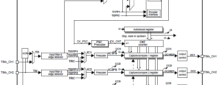
We already dealt with four registers for generating time bases. Apart from those we need a few more registers for PWM generation. Actually three sets of registers are needed to be dealt with. For advance timers, we will need to handle one more register for dead time and other purposes apart from the other three.
Firstly I will introduce the timer capture/compare mode register set. This set comprises of two separate registers TIMx_CCMR1 and TIMx_CCMR2. TIMx_CCMR1 controls capture/compare channel 1 and 2 while channel 3 and 4 are controlled by TIMx_CCMR2.
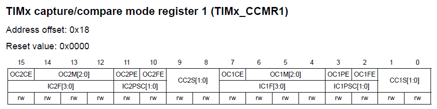
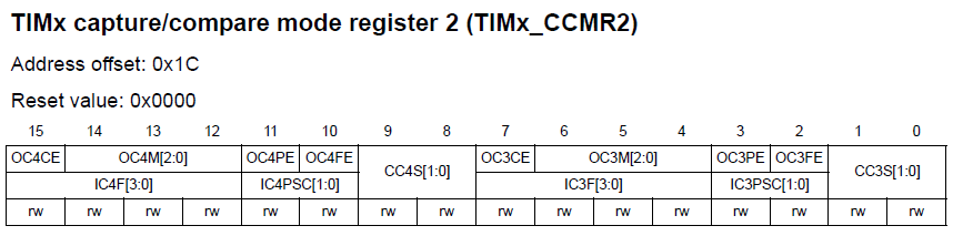
Please note that unlike other registers the CCMR registers have dual role and so the register maps have two separations. The top rows of these registers are for output/compare mode while the bottom layers are for input capture mode. CCxS bits of these registers determine the corresponding capture/compare channel’s I/O direction. For PWM mode these bits will be zero. The next stuff that we need to set in these registers are OCxM bits. These bits should be set either as 110 or 111 for PWM mode. The difference in these two bit settings is the PWM output type – i.e. normal PWM or inverted PWM.
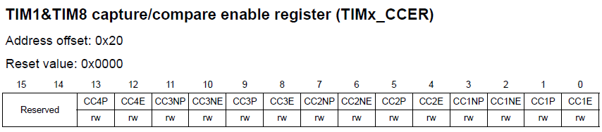
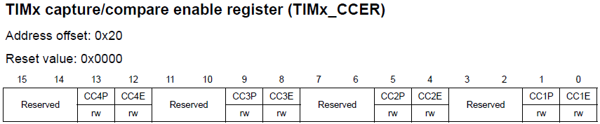
The next set of registers we will be dealing with are the TIMx_CCER registers. For all timers their bit orientations are same but advance timers have additional bits for additional functionalities. The purposes of these registers are simply enabling the desired capture/compare channels and setting their polarities.
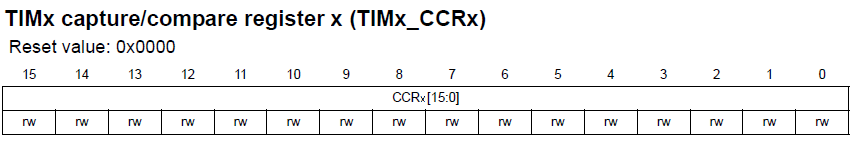
For every timer except the basic ones, there are four capture/compare registers TIMx_CCRx which correspond to four capture/compare channels. Changing the values in them during compare mode allows us to change PWM width or duty cycle. The value that will be set in the TIMx_ARR register will correspond to maximum PWM count or 100% duty cycle. PWM generation is accomplished by comparing the values in TIMx_CCRx registers and TIMx_CNT register. Note that complementary channels have no such registers and that’s because they output complementary signals of their respective ordinary channels.
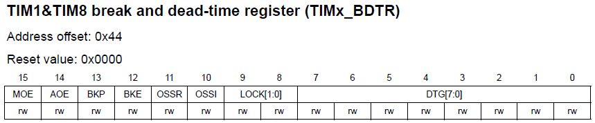
The registers I mentioned so far are common to all timers with capture/compare functionalities. Using them will allow us to accomplish common PWM-related tasks. However there is one more register that we will be needing to handle for more advanced tasks and so it is available only in advanced timers. This register is called Timer Brake and Dead Time Register, TIMx_BDTR. It is important to note that when using advanced timers for PWM generation the MOE bit should be set or else there will be no PWM output.
Since PWM generation and input capture are alternative functions of a GPIO pin, we need to enable and use AFIO registers as well for alternative functions of those pins. Provided it is supported, with AFIO registers we can remap/reposition default PWM/input capture pins to some other pins. AFIO_MAPR and AFIO_MAPR2 registers are used for such purposes.


Code Examples
MikroC PWM Library Example
All MikroC compilers come with PWM libraries. MikroC for ARM has PWM libraries for different variants of ARM chips – Stellaris M3s, M4s and STM32s. We are only concerned with STM32 variants. Only four functions are what are needed to be understood for using this library and these are as follows:
- PWM_TIMn_Init – initializes timer module in PWM mode by setting desired PWM frequency.
- PWM_TIMn_Set_Duty – sets PWM duty, PWM type and channel.
- PWM_TIMn_Start – starts respective timer module in PWM mode.
- PWM_TIMn_Stop – stops respective timer module.
As you can see these built-in library functions are very easy to get started with. However be sure of pin remapping. Random pin remapping may lead to undesired problems. Remember pins are mapped in groups. This is the common mistake most people make with PWM library.
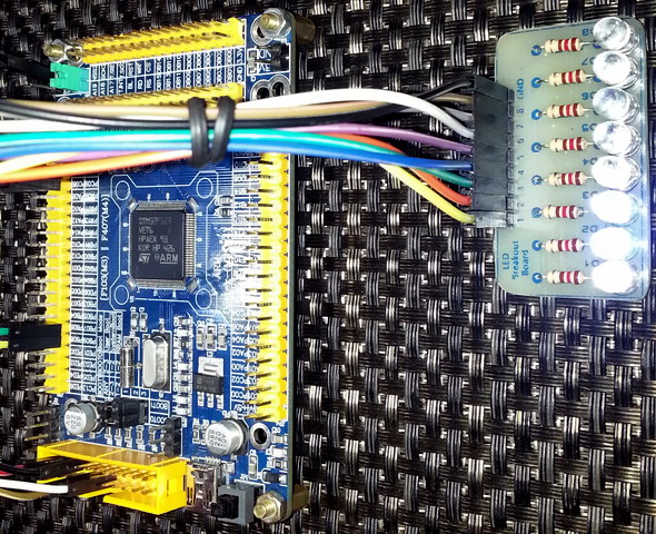
The code example for this demo is a glowing-fading running light. General purpose timers 3 and 4 are used to generate 6 kHz PWMs in eight channels. At any instance two adjacent LEDs will glow and fade opposite to each other. The brightness of one will gradually increase with the gradual decrement of the pervious LED’s brightness.
Note that in the code I didn’t set the AFIO registers and I also didn’t enable the timer APB buses. This is the advantage of using MikroC libraries. The PWM library took care of these.
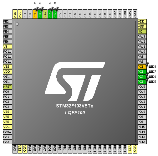
The following hardware setup is used for this demo:
unsigned int pwm_val = 0;
void setup();
void setup_PWMs();
void main()
{
unsigned int i = 0;
setup();
while(1)
{
for(i = 0; i <= pwm_val; i++)
{
PWM_TIM4_Set_Duty(i, _PWM_INVERTED, _PWM_CHANNEL1);
PWM_TIM4_Set_Duty(i, _PWM_NON_INVERTED, _PWM_CHANNEL2);
delay_us(200);
}
for(i = 0; i <= pwm_val; i++)
{
PWM_TIM4_Set_Duty(i, _PWM_INVERTED, _PWM_CHANNEL2);
PWM_TIM4_Set_Duty(i, _PWM_NON_INVERTED, _PWM_CHANNEL3);
delay_us(200);
}
for(i = 0; i <= pwm_val; i++)
{
PWM_TIM4_Set_Duty(i, _PWM_INVERTED, _PWM_CHANNEL3);
PWM_TIM4_Set_Duty(i, _PWM_NON_INVERTED, _PWM_CHANNEL4);
delay_us(200);
}
for(i = 0; i <= pwm_val; i++)
{
PWM_TIM4_Set_Duty(i, _PWM_INVERTED, _PWM_CHANNEL4);
PWM_TIM3_Set_Duty(i, _PWM_NON_INVERTED, _PWM_CHANNEL1);
delay_us(200);
}
for(i = 0; i <= pwm_val; i++)
{
PWM_TIM3_Set_Duty(i, _PWM_INVERTED, _PWM_CHANNEL1);
PWM_TIM3_Set_Duty(i, _PWM_NON_INVERTED, _PWM_CHANNEL2);
delay_us(200);
}
for(i = 0; i <= pwm_val; i++)
{
PWM_TIM3_Set_Duty(i, _PWM_INVERTED, _PWM_CHANNEL2);
PWM_TIM3_Set_Duty(i, _PWM_NON_INVERTED, _PWM_CHANNEL3);
delay_us(200);
}
for(i = 0; i <= pwm_val; i++)
{
PWM_TIM3_Set_Duty(i, _PWM_INVERTED, _PWM_CHANNEL3);
PWM_TIM3_Set_Duty(i, _PWM_NON_INVERTED, _PWM_CHANNEL4);
delay_us(200);
}
for(i = 0; i <= pwm_val; i++)
{
PWM_TIM3_Set_Duty(i, _PWM_INVERTED, _PWM_CHANNEL4);
PWM_TIM4_Set_Duty(i, _PWM_NON_INVERTED, _PWM_CHANNEL1);
delay_us(200);
}
};
}
void setup()
{
setup_PWMs();
}
void setup_PWMs()
{
unsigned int temp1 = 0;
unsigned int temp2 = 0;
temp1 = PWM_TIM3_Init(6000);
PWM_TIM3_Set_Duty(0, _PWM_NON_INVERTED, _PWM_CHANNEL1);
PWM_TIM3_Set_Duty(0, _PWM_NON_INVERTED, _PWM_CHANNEL2);
PWM_TIM3_Set_Duty(0, _PWM_NON_INVERTED, _PWM_CHANNEL3);
PWM_TIM3_Set_Duty(0, _PWM_NON_INVERTED, _PWM_CHANNEL4);
PWM_TIM3_Start(_PWM_CHANNEL1, &_GPIO_MODULE_TIM3_CH1_PC6);
PWM_TIM3_Start(_PWM_CHANNEL2, &_GPIO_MODULE_TIM3_CH2_PC7);
PWM_TIM3_Start(_PWM_CHANNEL3, &_GPIO_MODULE_TIM3_CH3_PC8);
PWM_TIM3_Start(_PWM_CHANNEL4, &_GPIO_MODULE_TIM3_CH4_PC9);
temp2 = PWM_TIM4_Init(6000);
PWM_TIM4_Set_Duty(0, _PWM_NON_INVERTED, _PWM_CHANNEL1);
PWM_TIM4_Set_Duty(0, _PWM_NON_INVERTED, _PWM_CHANNEL2);
PWM_TIM4_Set_Duty(0, _PWM_NON_INVERTED, _PWM_CHANNEL3);
PWM_TIM4_Set_Duty(0, _PWM_NON_INVERTED, _PWM_CHANNEL4);
PWM_TIM4_Start(_PWM_CHANNEL1, &_GPIO_MODULE_TIM4_CH1_PB6);
PWM_TIM4_Start(_PWM_CHANNEL2, &_GPIO_MODULE_TIM4_CH2_PB7);
PWM_TIM4_Start(_PWM_CHANNEL3, &_GPIO_MODULE_TIM4_CH3_PB8);
PWM_TIM4_Start(_PWM_CHANNEL4, &_GPIO_MODULE_TIM4_CH4_PB9);
if(temp2 >= temp1)
{
pwm_val = temp2;
}
else
{
pwm_val = temp1;
}
}

Demo video link: https://www.youtube.com/watch?v=uxBXF32cAgQ.
There are few limitations of the PWM library. One is the inability to support complementary PWMs and its related stuffs in advance timers. Secondly unlike most other MCUs, maximum PWM duty cycle needs to be read in the software as there’s no fixed timer count value that corresponds to this. Thus you will need to know this value either with a USART or a LCD even if you are not planning to use one in your project. Now this is where we pay the price of getting things easily. Basically it is not MikroE’s fault. STM32 timers are made in such a way and we’ll see why in the next example codes.
|
|
well done sir
How to set the PWM with Center aligned mode ?
Read this app note: http://www.st.com/web/en/resource/technical/document/application_note/DM00042534.pdf
Thanks,
Now need the sample code to change the CMS bits different from ’00’
Great tutorials! Best I’ve found so far.
Thanks…. 🙂
first of all i like to say a million thanks for this tutorial and i have been waiting for this
tutorial i am your biggest fan in stm32 programming for there is little information about it on the web you’ve motivated me to keep having interest in on knowing about the 32bit micros
Thanks…. People like you keeps me going…. 🙂
Pingback: STM32 Timers - Arduino collector blog