STM32 Timers
|
|
Output Compare Mode (PWM) Example
Sometimes a programmer needs to get out of the luxury of prebuilt compiler libraries and apply his/her skills. I pointed out some limitations of MikroC compiler’s PWM library and so we need to go around to avoid these limitations. By this way we will have a good understanding of the output compare mode (A.K.A PWM mode) and also optimize coding as per need.
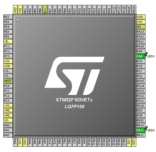
Firstly check out the code. You’ll notice that GPIO pins are setup as AFIO push-pull output pins and that’s because PWM mode is the alternative functionality of an I/O pin. Note that unlike timer 8 in which it is not possible, timer 1 channels can be remapped. However I didn’t apply remapping for the sake of simplicity.
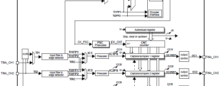
In this example, both advance timers of STM32F103VET6 micro are used. The PWM outputs have a common frequency and it is 45 kHz. The PWM frequency can be calculated just like what we saw in time-base generation examples.
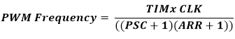
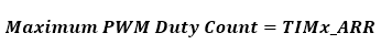
The maximum duty cycle count will be equal to the value that will be set in the timer auto-reload register, TIMx_ARR. In my example, I set PSC zero and ARR 1599 and so now you can see why the PWM frequency is 45 kHz. TIM1_ARR and TIM8_ARR registers are set 1599. Thus 100% duty cycle equals 1599 count, 50% duty cycle equals 800 counts and so forth. As said before, PWM is achieved by comparing counts in the TIMx_CCRn and TIMx_CNT registers. All channels of a timer will have the same PWM frequency but their duty cycles may be different.
The following lines of code set these parameters.
set_TIM1_counting_direction(up_counting);
TIM1_ARR = 1599;
TIM1_PSC = 0;
Then the following code states PWM parameters. PWM mode simply states whether or not to generate inverted PWM. The code also states which PWM channel to use and what should be its polarity. Finally it enables some controls to enable PWM generation.
set_TIM1_OC1_compare_mode(PWM_mode_1);
set_TIM1_CC1_state_and_polarity(enable, active_high);
enable_TIM1_main_output(true);
set_TIM1_CC_preload_control(true);
set_TIM1_auto_reload_preload_mode(true);
For PWM modes interrupts are not necessary as PWM generation is an independent process. To control PWM duty cycle, we only need to load values to TIMx_CCRn, anything between 0 to TIMx_ARR value.
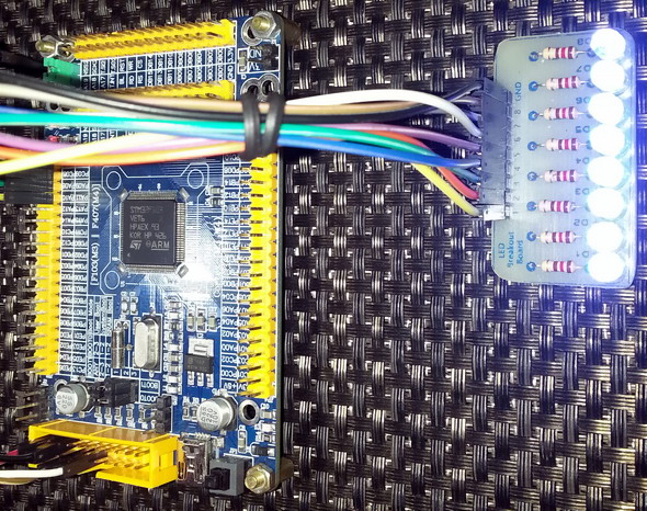
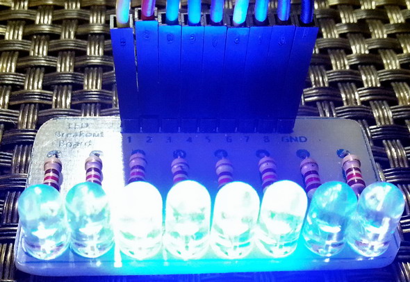
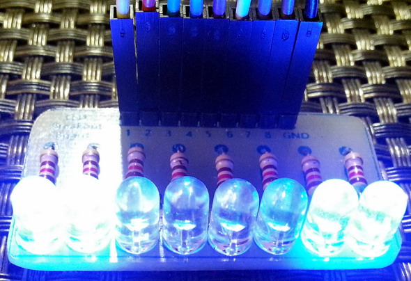
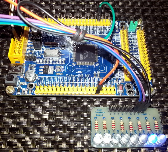
The following hardware setup is used:
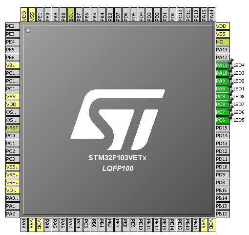
The code simply brightens and dims eight LEDs connected to timer PWM channels.
#include "TIM_common.h"
#include "TIM1.h"
#include "TIM8.h"
#include "GPIO.h"
#include "AFIO.h"
void setup();
void setup_IO();
void setup_TIM1();
void setup_TIM8();
void main()
{
unsigned int duty = 0;
setup();
while(1)
{
while(duty < 1600)
{
TIM1_CCR1 = duty;
TIM1_CCR2 = duty;
TIM1_CCR3 = duty;
TIM1_CCR4 = duty;
TIM8_CCR1 = duty;
TIM8_CCR2 = duty;
TIM8_CCR3 = duty;
TIM8_CCR4 = duty;
duty++;
delay_ms(4);
}
while(duty > 0)
{
TIM1_CCR1 = duty;
TIM1_CCR2 = duty;
TIM1_CCR3 = duty;
TIM1_CCR4 = duty;
TIM8_CCR1 = duty;
TIM8_CCR2 = duty;
TIM8_CCR3 = duty;
TIM8_CCR4 = duty;
duty--;
delay_ms(4);
}
};
}
void setup()
{
setup_IO();
setup_TIM1();
setup_TIM8();
}
void setup_IO()
{
AFIO_enable(true);
AFIO_remap(TIM1_not_remapped);
enable_GPIOA(true);
setup_GPIOA(8, (AFIO_PP_output | output_mode_high_speed));
setup_GPIOA(9, (AFIO_PP_output | output_mode_high_speed));
setup_GPIOA(10, (AFIO_PP_output | output_mode_high_speed));
setup_GPIOA(11, (AFIO_PP_output | output_mode_high_speed));
enable_GPIOC(true);
setup_GPIOC(6, (AFIO_PP_output | output_mode_high_speed));
setup_GPIOC(7, (AFIO_PP_output | output_mode_high_speed));
setup_GPIOC(8, (AFIO_PP_output | output_mode_high_speed));
setup_GPIOC(9, (AFIO_PP_output | output_mode_high_speed));
}
void setup_TIM1()
{
enable_TIM1(true);
enable_TIM1_counter(false);
set_TIM1_counting_direction(up_counting);
TIM1_ARR = 1599;
TIM1_PSC = 0;
set_TIM1_OC1_compare_mode(PWM_mode_1);
set_TIM1_OC2_compare_mode(PWM_mode_1);
set_TIM1_OC3_compare_mode(PWM_mode_2);
set_TIM1_OC4_compare_mode(PWM_mode_2);
set_TIM1_CC1_state_and_polarity(enable, active_high);
set_TIM1_CC2_state_and_polarity(enable, active_high);
set_TIM1_CC3_state_and_polarity(enable, active_high);
set_TIM1_CC4_state_and_polarity(enable, active_high);
enable_TIM1_main_output(true);
set_TIM1_CC_preload_control(true);
set_TIM1_auto_reload_preload_mode(true);
enable_TIM1_counter(true);
}
void setup_TIM8()
{
enable_TIM8(true);
enable_TIM8_counter(false);
set_TIM8_counting_direction(down_counting);
TIM8_ARR = 1599;
TIM8_PSC = 0;
set_TIM8_OC1_compare_mode(PWM_mode_1);
set_TIM8_OC2_compare_mode(PWM_mode_1);
set_TIM8_OC3_compare_mode(PWM_mode_2);
set_TIM8_OC4_compare_mode(PWM_mode_2);
set_TIM8_CC1_state_and_polarity(enable, active_low);
set_TIM8_CC2_state_and_polarity(enable, active_low);
set_TIM8_CC3_state_and_polarity(enable, active_low);
set_TIM8_CC4_state_and_polarity(enable, active_low);
enable_TIM8_main_output(true);
set_TIM8_CC_preload_control(true);
set_TIM8_auto_reload_preload_mode(true);
enable_TIM8_counter(true);
}
Demo video link: https://www.youtube.com/watch?v=IwfpD67HUMQ.
Advance Timer Complementary PWM Generation Example
We already know that advance timers have the ability to generate complementary/opposite PWM waveforms. Such PWMs have many applications in power electronics sector. Motor control, inverters and DC-DC converters are a few good examples. In any advance timer there are three pairs of complementary PWM channels denoted as CHx and CHxN. The N signifies the inverted characteristic of that channel. Additionally there are options to add dead-time between these complementary waveforms and do some other advanced tasks.
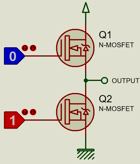
Dead time automatically adds a delay between waveform transitions. Consider a half-bridge MOSFET configuration. Surely you’ll never want to turn on both MOSFETs during transitions as it will lead to a temporary short circuit between source and ground, and also lead to unnecessary heating of the MOSFETs. By applying dead-time this can be avoided. Luckily STM32 advance timers have this feature.
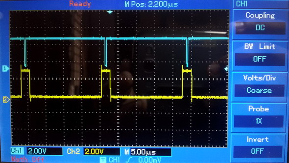
In terms of programming, complementary PWM generation is not so much dissimilar to ordinary PWM generation. Each and every setup is same except in the case of complementary PWM, we need to enable complementary channels and setup dead-time setting if needed.
In this example only one complementary pair (CH1 and CH1N) of timer 1 is used. Note that TIM1_CCR1 is responsible for the PWM duty cycle of both of these outputs. You’ll notice one LED will brighten complementarily to another. The effect of applying dead-time will be visible when you observe the waveforms.
The hardware setup is like this:
#include "TIM_common.h"
#include "TIM1.h"
#include "GPIO.h"
#include "AFIO.h"
void setup();
void setup_IO();
void setup_TIM1();
void main()
{
unsigned int duty = 0;
setup();
while(1)
{
while(duty < 1600)
{
TIM1_CCR1 = duty;
duty++;
delay_ms(1);
}
while(duty > 0)
{
TIM1_CCR1 = duty;
duty--;
delay_ms(1);
}
};
}
void setup()
{
setup_IO();
setup_TIM1();
}
void setup_IO()
{
AFIO_enable(true);
AFIO_remap(TIM1_not_remapped);
enable_GPIOA(true);
setup_GPIOA(8, (AFIO_PP_output | output_mode_high_speed));
enable_GPIOB(true);
setup_GPIOB(13, (AFIO_PP_output | output_mode_high_speed));
}
void setup_TIM1()
{
enable_TIM1(true);
enable_TIM1_counter(false);
set_TIM1_counting_direction(up_counting);
TIM1_ARR = 1599;
TIM1_PSC = 0;
set_TIM1_OC1_compare_mode(PWM_mode_1);
set_TIM1_CC1_state_and_polarity(enable, active_low);
set_TIM1_CC1_complementary_output_state_and_polarity(enable, active_low);
set_TIM1_off_state_selection_for_run_mode(enable);
set_TIM1_dead_time(77);
enable_TIM1_main_output(true);
set_TIM1_CC_preload_control(true);
set_TIM1_auto_reload_preload_mode(true);
enable_TIM1_counter(true);
}


Demo video link: https://www.youtube.com/watch?v=wfwlfv2-_uY.
|
|
well done sir
How to set the PWM with Center aligned mode ?
Read this app note: http://www.st.com/web/en/resource/technical/document/application_note/DM00042534.pdf
Thanks,
Now need the sample code to change the CMS bits different from ’00’
Great tutorials! Best I’ve found so far.
Thanks…. 🙂
first of all i like to say a million thanks for this tutorial and i have been waiting for this
tutorial i am your biggest fan in stm32 programming for there is little information about it on the web you’ve motivated me to keep having interest in on knowing about the 32bit micros
Thanks…. People like you keeps me going…. 🙂
Pingback: STM32 Timers - Arduino collector blog