Using TC74 (Microchip) thermal sensor for temperature measurement
|
|
The TC74 chip is a serially accessible, digital temperature sensor from Microchip Technology that acquires and converts temperature information from its onboard solid-state sensor with a resolution of 1°C. The temperature is available as an 8-bit digital word stored in its internal temperature register, which is accessible through a 2-wire I2C compatible serial bus. This tutorial describes how to use the TC74 sensor with a PIC microcontroller to measure the surrounding temperature.

Using TC74 sensor for temperature measurement
Theory
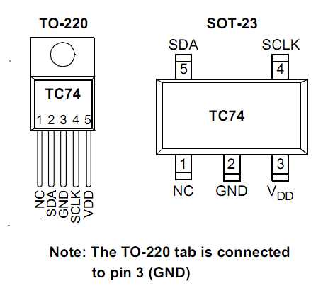
The TC74 digital temperature sensor is available in SOT-23 and TO-220 packages. The communication with the device is accomplished via a 2-wire I2C compatible serial bus. Temperature resolution is 1°C and conversion rate is a nominal 8 samples/sec. The pin diagram of TC74 chip is shown below for reference.

Pin diagram of TC74
The TC74 stores the measured temperature into its 8-bit internal register as 2’s complement binary format. The most significant bit is the sign bit, which is set to 1 for negative temperatures. Therefore, the maximum measurable positive temperature is + 127 °C (0111 1111). The TC74 has also got another 8-bit Read/Write Configuration Register (RWCR) that is used to put the device into a low power (IDD = 5 µA, typical) Standby mode. In this mode, the A/D converter is halted and the temperature data registers are frozen. Bit 7 of RWCR must be set to put TC74 into Standby mode.

Temperature conversion table and internal registers
Serial port operation
The Serial Clock input (SCLK) and bidirectional data port (SDA) form a 2-wire bidirectional serial port for communicating with the TC74. The port is I2C compatible and all transfers take place under the control of a host, usually a microcontroller. The host microcontroller provides the clock signal for all the data transfers and the TC74 always operates as a Slave. The default 7-bit I2C address of TC74 is 1001 101b. However, 7 other address options are also available which can be identified from the part number of the device. For example, I have got a TC74A0 in TO-220 package. A0 corresponds to the device address 1001 000b. Similarly, TC74A3 has its I2C address 1001 011b. Refer the datasheet for further details. If you are not familiar with I2C protocol, please read my article, Inter-Integrated Circuit (I2C) communication in PIC. Reading temperature from a TC74 device through I2C port involves the following steps:
- The host microcontroller issues a Start condition followed by the address byte. The address byte consists of the 7-bit slave address and a Read/Write bit (R/W). The R/W bit is always ‘0’ (Write) in the first phase.
- If the received 7-bit address matches with its own slave address, the TC74 responds with an acknowledge pulse.
- The host microcontroller next sends the command byte to TC74 to indicate which register it wants to access. For reading the temperature, the command byte should be 00h. The TC74 responds with an acknowledge pulse.
- The host microcontroller issues a new Start condition because the direction of data transfer is now going to be changed. The new address byte with R/W bit 1 is sent by the host, which is acknowledged by the slave.
- The TC74 transmits the 8-bit temperature data from the temperature register. Upon receiving the byte, the host doesn’t acknowledge, but generates a Stop condition.
Circuit diagram
I am using PIC18F2550 to demonstrate here, but it can be implemented with any other smaller size PIC microcontrollers that support I2C communication. The temperature is read from the TC74 sensor and displayed on a character LCD. Don’t forget to put two pull-up resistors (1K) on SDA and SCL lines of I2C bus. The PIC18F2550 microcontroller used in this experiment is from the StartUSB for PIC board.

Circuit diagram

Circuit setup on breadboard

TC74 temperature sensor
Software
The firmware for PIC18F2550 is developed in C using mikroC Pro for PIC compiler. The compiler provides the built-in library for I2C support. The microcontroller reads the temperature word from the TC74’s internal temperature register and displays it on the LCD. The following program works for the entire operating range of TC74 (-40 °C to 125 °C).
/* Project: Using TC74 with PIC microcontroller for temperature measurement MCU: PIC18F2550 on-board StartUSB for PIC Clock 48.0 MHz using HS + PLL MCLR Enabled */ // Define LCD module connections. sbit LCD_RS at RC6_bit; sbit LCD_EN at RC7_bit; sbit LCD_D4 at RB4_bit; sbit LCD_D5 at RB5_bit; sbit LCD_D6 at RB6_bit; sbit LCD_D7 at RB7_bit; sbit LCD_RS_Direction at TRISC6_bit; sbit LCD_EN_Direction at TRISC7_bit; sbit LCD_D4_Direction at TRISB4_bit; sbit LCD_D5_Direction at TRISB5_bit; sbit LCD_D6_Direction at TRISB6_bit; sbit LCD_D7_Direction at TRISB7_bit; // End LCD module connection definition unsigned char Temp; unsigned short num; const int TC74A0 = 0x90; void check_device(unsigned short dev_address){ I2C1_Start(); if (I2C1_Wr(dev_address)){ Lcd_Out(1,1,"Device not found"); } else Lcd_Out(1,1,"TC74 device"); I2C1_Stop(); } unsigned short Read_Temp(){ unsigned short result; I2C1_Start(); // Issue start signal I2C1_Wr(TC74A0); // Address + Write bit I2C1_Wr(0x00); // Read Temp I2C1_Repeated_Start(); // Issue start signal I2C1_Wr(TC74A0+1); // Address + Read bit result = I2C1_Rd(0u); return result; } char temperature[] = " 000 C"; void main() { CMCON = 0x07; // Disable comparators ADCON1 = 0x0F; // Disable Analog functions TRISA = 0x00; TRISC = 0x00; TRISB = 0x00; I2C1_Init(100000); // Initiate I2C Lcd_Init(); // Initialize LCD Lcd_Cmd(_LCD_CLEAR); // CLEAR display Lcd_Cmd(_LCD_CURSOR_OFF); // Cursor off Lcd_Out(1,1,"Testing TC74"); Lcd_Out(2,1,"Thermal sensor"); Delay_ms(1000); Lcd_Cmd(_LCD_CLEAR); do { check_device(TC74A0); num = Read_Temp(); // Check for negative temperature if (num > 127) { temperature[0] = '-'; num = ~num +1; } else temperature[0] = '+'; temperature[1] = num/100 + 48; temperature[2] = (num/10)%10 + 48; temperature[3] = num%10 + 48; temperature[5] = 223; // eliminate 0s at beginning if (temperature[1] == '0') { temperature[1] = ' '; if (temperature[2] == '0') temperature[2] = ' '; } Lcd_Out(2,4,temperature); Delay_ms(500); } while(1); } |
Download the mikroC source and HEX files
Output
The following pictures show the device displaying both positive and negative temperatures. The tip of a hot soldering rod saturates the sensor at 127 °C. To test the negative temperature reading, the device is put inside the freezer.

Displaying room temperature

Maximum measurable temperature

Measuring negative temperature inside the freezer
|
|
Hello, this is a wonderful project and I will like to adapt it somewhat. Using the same temperature sensor but a different microcontroller (PIC18F2420). I have tried to run the C code provided in MPLABx environment but getting errors. Can you advise how to go about this.
It,s works til 83 degrees and than the LCD display say,s no device.
Can you tell me waht,s wrong?
It would be hard to say without looking at your setup. How did you get the 83 degrees temperature for your experiment?
I have made it from your schematic from your website.
I found the solution with experimenting.
With replacing the pull-up resistors from 1KΩ to 4,7 kΩ.
Now it,s works to 114 degrees celsius.
Can you do me a huge favor and send me the .hex for the TC74A2 5.0VAT.
I’m just a beginner and programming is a step too far for me.
I have already 5 projects made from your site.
And they all work fine.
My compliments for your work.
Can you do me a huge favor and send me the .hex for the TC74A2 5.0VAT.
Can you do me a huge favor and send me the .hex file for the TC74A2 5.0VAT.
see datasheet! the address for TC74A25.0VCT is 1001 010. convert to hex or decimal and replace the value in const int TC74A0: const int TC74A2 = new value converted for hex or decimal
hello, nice to meet you, i have tried the code and but is given me error that the device not found. And can i used PIC 16f877A for the same code? thanks.
Hi! I tried to implement your circuit in Proteus by means of source and cof/hex files you provide for downloading. Unfortunately, it doesn’t work. The code hangs while attempting to execute I2C1_Start in check_device function. Could you possibly explain why?
Also, is it a good idea to place I2C1_Stop at the very end of Read_Temp function?
Thank you in advance!
Hi
Thank you about your excellent website.it’s very useful
This project was very useful for me but your program has a tiny problem :
in the “” read_temp “” function after you got the result , you must stop the i2c with i2c_stop(); if you don’t do it,your program (after going in this function for the first time) can’t use the i2c protocol again.you can repair it by steps below :
1) at the program (wich shown in the site) where function “unsigned short Read_Temp(){ ” is developed
2)after result = I2C1_Rd(u);
and before return result;
3) add I2C1_stop();
thank you for your site.
I’ll be happy to answer me by e_mail
Hi! Thank you for your reply. I am not trying to say that the code is wrong or anything like that. Obviously, I miss subtle details. However, I still can’t run the simulation in Proteus.
Please, help if possible. I could send you the Proteus project if it is necessary.
Regards, Konstantin
konstantinmetodiev@gmail.com
Hi! I dealt with the problem. In Proteus environment, the pull-up resistors’ properties must be set to digital. The code works great!
Regards!
hello..could we use LM35 as a replacement for TC74?
can the tc74 be replaced with lm35?
hello,,good day.
will the project still work the same if we will use TC74-5.0 VCTTR instead of VAT?
It should work. You may have to change the I2C address (const int TC74A0 = 0x90;) in the code to match with the correct device. See the datasheet page 9 for more details.
Hi,
I’m making a project with this sensor; I’ve got an A0 type. I’m trying to read temperature but it seems impossible. I don’t understand why. Could you help me? I’m using a PIC18F 4620; My program stops in the Read_Temp function and doesn’t exit never.
init () {
TRISCbits.TRISC3=1;
TRISCbits.TRISC4=1;
OpenI2C(SLAVE_7,SLEW_OFF );
}
unsigned char Read_Temp(){
unsigned char result;
StartI2C(); // Issue start signal
WriteI2C(0x90); // Address + Write bit
WriteI2C(0x00); // Read Temp
RestartI2C(); // Issue start signal
WriteI2C(0x91); // Address + Read bit
result = ReadI2C();
return result;
}
I hope you can help me, ThankYou
p.s. I’m sorry for my english..
If you are using A0 type, my code should work. Make sure you connected the I2C pins of PIC18F4620 correctly.
That’s great! Thank you for the prompt help.
Kind regards,
Miklos
Hi,
I’m a newbee for uControllers and unfortunately I have only a TC74A2 5.0VAT sensor. Which part of the original program do I have to modify for the proper functionality.
Thanks in advance,
Miklos
@Miklos,
The I2C slave address of TC74A2 5.0VAT is 0x92. So you need to change it in the following line of the code:
const int TC74A0 = 0x90;
Replace 0x90 by 0x92, and it should work.
Good day,
I am enjoying working with this project, but I would like to be able to do a conditional operator to set a temperature point where something happens:
Psuedo
When temp >= 28’C then print additional message to LCD;
When temp >= 28’C then set port to start fan;
Simple, yes but I can’t figure out how to work with tha data types. If I convert temperture to int then it stays at a value of 36.
If I just fo a conditional operator ie:
void checktemp(){
if (temperature >=28) Lcd_Out(2,6,”T HIGH!”);
}
Then when the temp on the display is no where near 28and the additional message is already typed. Any help please, it would be greatly appreciated.
Regards
Michael
PS: I am in the process of converting to 3v3 uMicro. So I will let you know how the project works on low voltage J type PICs.
Hi,
Thanks for the great project, got it working. I was however perplexed by a problem I first experienced when trying to get the code to work on a PIC16F887 – I might be mising somthing but as far as I could tell the I2C capability of the the 16F887 and the PIC18F2550 were the same. Interestingly, the 16F887 kept gettting the device not found error wheres the PIC18f2550 worked first time … weird.
Regards
Michael
Hi,
Has this been tested on SMBUS – I would like to use this is in a 3v3 application ?
Regards
Michael
Pingback: I liked this: How to use Microchip’s TC74 sensor for temperature measurement | Road to 2012
Pingback: Electronics-Lab.com Blog » Blog Archive » How to use Microchip’s TC74 sensor for temperature measurement