Programmable digital timer switch using a PIC Microcontroller
|
|
Digital timer switches are used to control the operation of electrical devices based on a programmed schedule. This project describes a programmable digital timer based on the PIC16F628A microcontroller that can be programmed to schedule the on and off operation of an electrical appliance. The appliance is controlled through a relay switch. This timer switch allows you to set both on and off time. That means, you can program when do you want to turn the device on and for how long you want it to be remained on. The maximum time interval that you can set for on and off operation is 99 hours and 59 minutes. The project provides an interactive user interface using a 16×2 character LCD along with 4 push buttons.

Programmable digital timer
Note: (June 30, 2016) A revised version of this project with added new features is posted here.
Circuit Design
The circuit diagram of this project is shown below. A 5V relay is driven by a PN2222 transistor that is controlled by RB3 pin of PIC16F628A. Digital inputs from the 4 push buttons are read through port pins RA2, RA3, RA4, and RB0. The functions of these push buttons are discussed in the operation section below. A standard 16×2 character LCD is used in the project to display the device status, program menu and time. The LCD is operated in 4-bit mode, therefore, only 6 I/O pins of PIC16F628A are required to drive it. A piezoelectric buzzer provides audible tone when the timer is started and stopped. It also beeps when the device is turned on or off. The + 5V power supply for the circuit is derived from a LM7805 regulator IC. The input to the regulator is given from a 9V DC wall adapter.


In the circuit diagram, the pins 15 and 16 of the LCD are shown open. These pins are available only in those LCDs that have a back light illumination LED. The pins 15 and 16 are the anode and the cathode of the LED. If your LCD has the back light LED, you can connect these pins to the power supply terminals with a 39 Ohm resistor in series. The backlight LED enhances the readability of the LCD display in low illumination condition.
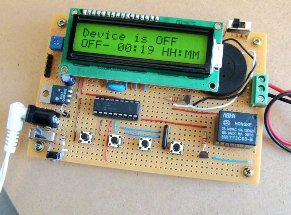
The complete circuit soldered on a general purpose prototyping circuit board is shown below.


Operation of the timer
The timer gets inputs from the 4 push buttons. Their functions are described as follows:
- ON/OFF TIME : This timer device allows you to set both on and off time. When the timer is initially powered on, the device is in off condition and both on and off times are 0. Pressing this button, you can switch between the on and off time on the display.
- SELECT : This allows you to select between the on and off time settings as well as hour and minute digits. The selected digit is incremented by pressing the ON/OFF TIME button.
- ENTER : When the appropriate hour and minutes are selected, pressing ENTER finalize the corresponding on or off time.
- START/STOP is to start or stop the timer. If the timer is already on, you can stop it at anytime during its operation by pressing this button.
Now lets see how it works. Suppose, the device connected to the relay switch is needed to be turned on after 2 minutes. Further, once it is turned on, it is required to be on for next 20 minutes. In this case, the off time is 00:02 and the on time is 00:20, in hh:mm format. Once the timer is started, the device will be turned on after 2 minutes and remained on for 20 minutes. After that it will be turned off again. The following video shows how to do this.
Software
The firmware is developed using the MikroC Pro for PIC compiler.
Download the Source Code

Digital timer switch
Update (04/12/2013)
Mark Weir from Australia sent us his revision of our Programmable digital timer switch project. He modified the original code, which was written for PIC16F628A, to incorporate it with PIC18F4620 microcontroller, while hardware and overall functionality remain the same.

Digital timer using PIC18F4620
Here is a link to download his modified version of the firmware written in MikroC compiler.
|
|
There are a couple things not mentioned in this project. I built 2 of the revised boards but they did not work. I used a TL866A programmer to burn my PIC16F628A using the hex file in the zipped firmware file but when I put it in the socket on the boards they did not work. It turned out that the reason they did not work was because the TL866 does not set the fuses for the PIC or at least set them correctly. When I moved to my K150 programmer and software and set the fuses they worked.
What I would like to know is how to modify this (code) so it is seconds and minutes instead of hours and minutes. Can you cover that?
Thank you.
Since you offer a pc board for this project may I suggest that you post a picture of that board (completed or blank) and also a parts list that you used to build it. I am curious what 2 pin tactile switches you used and how long was the actuator shaft? Also, why did you use 1µf MLCC capacitors on each side of the 7805 since the datasheet uses 1µf tantalums?
Thank you.
Are the pc board gerbers available for this project? Are the project files (Proteus or Eagle or KiCad) available? I am looking to build a 0 to 99 second count downtimer rather than 1 to 99 minute timer like this one. It would be nice if it was 1 second to 99 minutes.
Thank you.
I have seen people saying the code doesn’t work. I believe they don’t know how to use mikroC. Follow this step (code doesn’t have any error):
1 – Open MikroC and import source code.
2 – Click on “Project (On top bar)” and then click “Edit Project”
3 – A new window popped up has MCU tab change mcu to PIC16F628A.
4 – Change Oscillator Frequency to 4MHz.
That’s all ! Click ok.
Now run on your simulation or proto-type model it will work.
Good day.
Hi, I would like to know if the code still available? Where can I download it? Please send me the link.
Thank you.
Can you please provide a 4 digit 7 segment display clock by 16F628 for1 inch or bigger size display with adjustable hour and minute setting or any link from where circuit and firmware will be available,
Hi Friend
You have this project in Proteus to send for me?
Thanks
Can you send me the list of the components used in this project?
u.m.okul@hotmail.com
Hello, I intend to use this device to control the flow of electricity for an arduino board however I need a parts list. If someone would be kind enough to help me out with that and email it to me that would be great.
peterdoro@outlook.com
If you have the component list can you send it to my email? u.m.okul@hotmail.com
GOOD DAY!
I am very interested in bulding this project but when I tried programming the 16F628A with both .hex files provided – the basic one and the revised version one – I get nothing but errors. What can I do to program this chip correctly?
Hope someone has a working solution to this problem.
Thanks a million!!!!
hi could you use a 9v battery instead of a power supply on the wall thanks steve
Hai Sir,
same as your,s i need to program for 1 min display on lcd using timer,like 60,59,58,…….01,00
can u help me to get out this problem,
Sir, I tried to simulate the circuit in proteus. And it partially worked. I do have some doubts in my mind
When i Set the timer to 1 minute and started it really it turned of in 4 minutes.
When i set the timer to 2 minutes i mean after 8 minutes it turned off.
I dint know the pic programming . So i just wanted to ask whether you intentionally made such a 1:4 relation or in your actual circuit is it 1:1.
Thanks
sir can u tell me if i want if pv voltage full than timer is reset than how its possible
Pingback: PIC Programmable Relay Switch - Electronics-Lab
Can u sent this project report and proposal?
If Power is switched off , setting will be there or deleted from memory
Yes, cyclic version is required for watering the plants, please provide modified version as soon as possible
Hi “again 🙂 ” I have just read the previous comment and the answer you provided about the cyclic version i too have virtually no programming skills furthest i got was
10 PRINT “David” 20 GOTO 10
i want to run a charging system 10 hours on 10 hours off cyclic this cannot be acheived with a normal 24 hr timer so i would be gratefull if you could let me know when the cyclic version is available Best regards David
In two weeks, I will have a revised version ready.
Hi i need a timer circuit to control a siren or hooter for race start procedure. Siren need to beep on 10sec after startup of circuit for 3 secs. After 240sec it needs to beep 2 by 2secs off for 0.5 sec between beeps after 30sec needs 3 by 1sec beeps off for 0.5sec between beeps. And then stop as the race will start on last 3sec beep. Can you please help.
Circuit start 10sec delay first 3sec beep.
240sec 2 by 2sec beeps 0.5sec off between.
30sec 3 by 1sec beeps 0.5sec off between.
20 sec 1 by 3 sec beep and then circuit can stop. All driven by 12v dc.
hex file too large for a 628 which has only 2kb of code memory
Hi brilliant project excactly what ive been searching the net for please could you tell me the full component list Best regards David
Hi
From what I can understand the circuit from Mark Weir is cyclic with a clock display. Im not a programmer but im rather technical thus I can build and write software to chips and the reason for this writing is I live on a farm and every day I need to start up a generator and switch it off at a specific time once during day break and once at night . I was thinking about a high power remote control but that will also lack in consistency…..(old age keep on forgetting to do certain things) So I was thinking of a 24hour programmable clock that will start and stop this generator twice a day for me. If it is possible please help I like doing things for myself….. Thank you and God bless….. Regards Philip.
Philip,
This project does not have a real time clock chip. But your generator needs to be turned on and off after the same amount of time every day, then you can use a cyclic version of it. For example you can program it for 12 hours OFF time and 30 minutes ON time. Then it will turn on every 12 hours and runs for 30 minutes, and will repeat that. I am going to post the revised version of this project with cyclic feature soon.
Sir
i am not a programer but I want to make it. I purchase all the components and soldering it as is your diagram can you tell me how to program it. My email address is -srlpapuni@Gmail.com
Please help me i
Respected sir,
I made the circuit , but the hex file does not work . Please be kind enough to send me to the correct hex file.
ranveer.vibhute@gmail.com
You can see the source code is given you can re-compile it into hex. Not only this, you can also make changes to the program. Like you want LCD to display your name as a welcome message.
Respected SIR,
can u tell me What will be cost of this project?
pls reply.
ranveer.vibhute@gmail.com
Ranveer i think you’re from India,
I can tell you the cost of here Pakistan.
It should cost about 200-250 Rs..PKR
So i think yours 100-150 i exactly don’t know the difference.
Here microcontroller PIC16F628a is for RS 40
16×2 Character LCD is for RS 150
4pcs Button costs 20 Rs
Resistance, crystal etc cost about 20 RS
2n3904 Transistor 3 Rs
Piezo Buzzer 10Rs
Relay 15 Rs
Voltage regulator 7805 is for 7Rs
and thats all now you can add some cost of the housing of your project. I think you better know about that. 😉 Keep doing good project.
Yes,yes, yes…..
i make cyclic on off timer ,
I worked hard on this project from last 4 months. I want cyclic timer that repeats on off on off continuosly cycle and resets only when power fails or reset is pressed . So anybody needs on off unlimited cycle code then feel free to email me at hamidoon.174@gmail.com
Plz text me code.. hubaibkhan9@gmail.com
This site has a timer that repeats the cycle. http://projects22.cu.cc/lcd_egg_timer.php
Excellent project.
I rode and I will post some pictures.
It would be much better if you could also program the seconds and could see in countdown Ex: (HH: MM: SS)
Relay:
http://i1121.photobucket.com/albums/l510/ricardoams/IMG_20150417_182825382.jpg
Mounted circuit board:
http://i1121.photobucket.com/albums/l510/ricardoams/IMG_20150417_183116581.jpg
More Pictures:
http://i1121.photobucket.com/albums/l510/ricardoams/WP_20141223_01_00_45_Pro.png
http://i1121.photobucket.com/albums/l510/ricardoams/WP_20141222_16_36_37_Pro.png
http://i1121.photobucket.com/albums/l510/ricardoams/WP_20141223_00_56_04_Pro.png
Hey friend you did it real nice. I love the way you designed PCB for this. Do you have that PCB layout? can i have it?
salut
excellent travail et merci pour le partage mais sur isis 7 seulement l’écran qui est allumé et il n’y a rien d’autre.
je me demande si on peut exploiter RB1 (broche 7) qui est libre ou autre pour actionner un autre relais pour obtenir deux temporisation
1-start —————–> début décomptage premier temps (collage du relais 1 )
2 -fin premier tempo ———> décollage du relais 1
3- début décomptage deuxième temps (collage du relais 2 )
4-fin deuxieme tempo ———> décollage du relais 2
5- ATTENTE
merci d’avance
sir,
In mickro c , your digital timer program didn’t work.
Will u please help me
Please send your unlimited cycle code here or at
hassanuzaman@gmail.com
I want the little bit modification in this timer. Timer could able to hold the previous data untill the reset button is pressed or supply is disconnected. After that data will be again enter by the operator.
Dear sir,
I am extreemly in need of a humidity controller circuith relay by microcontroller, please help me out, humidity level will be controlled in a closed area by a relay. Best Regards.
Dear sir,
I am very much in need of a humidity controller by a relay, can u please help me out by providing this circuit by micrcontroller, witch wil controll humidity level in a cloaed area by relay. Best Regards.
Hello,
It’s a nice tutorial project, I simulated on ISIS and it works perfectly.
Now I’ll do it on my DEC_PIC.I’llgive you the result soon.Thanks a lot.
Kazdin.
Hello, please what is your relay for pcb Ricardo from Brazil?
I use one Relay 5V
Relay:
http://i1121.photobucket.com/albums/l510/ricardoams/IMG_20150417_182825382.jpg
Mounted circuit board:
http://i1121.photobucket.com/albums/l510/ricardoams/IMG_20150417_183116581.jpg
More Pictures:
http://i1121.photobucket.com/albums/l510/ricardoams/WP_20141223_01_00_45_Pro.png
http://i1121.photobucket.com/albums/l510/ricardoams/WP_20141222_16_36_37_Pro.png
http://i1121.photobucket.com/albums/l510/ricardoams/WP_20141223_00_56_04_Pro.png
Please delete my previos comment.
This timer works perfect i have swapt Start and Reset button. Thank you for sharing this project.
I have made this timer, but it seems to be a copyright protected project. Everytime i push start, i get a message -> Copyright embedded_lab.com and timer is not wotking of course. See video….
http://tinypic.com/player.php?v=33csuhu%3E&s=8#.VL5WutKG_Ag
My qustion to publisher is.. it is possible to get working HEX file for free or it is mandatory to donate?
Which compiler was used to assemble the hex?
Since the compiler i use is giving me error during the compile of this…
Maybe some is missing?
Regards
sir I use Pickit2 programmer for writing hex file but I face problem. when i imports the hex the pickit2 shown Cod Protect & when I trying to write hex then pickit2 shown varification failed. sir plz suggested me how to writ the hex, i regard to U…..
RB are U dead? I asked a question 06/01/2015 but till now U don’t any reply. U losing my time & money.
sir
plz send me correct hex file.
Hex file is correct.
Send me hex file..
Dear sir
I made the circuit , but the hex file does not work . Please be kind enough to send me to the correct hex file.my email: ashikbsl@live.com reguards!!!
U first load the hex file in pic flash file .
Than save hex .& retry by
hassanuzaman@gmail.com
I worked on this project and i found that a some basic features required, which weren’t found in current firmware for this project.
Not sure how to upload file here, but I added “seconds” in this timer, and unlimited cycles. I can send my version if anyone needs it.
michail.samolo, you could upload your version on the web somewhere and link it here, I would be more than happy to host the file on my website if you are not able to do so and I would be grateful to use your version of the code if you would be happy to share it. Contact me via email ben at benjaminmark dot net
I have tried to contact him through email but he has not responded. I would be happy to share his code here.
Please send your unlimited cycle code here or at bill_108@yahoo.com
Thanks
please send me your code me by mail for unlimited cycles
thanks
I would be very grateful if you can send me the hex file of your modified project. Sorry for my English . I am Brazilian.
Hi Michail Samolo ,Can you send your modified file with unlimited cyclic modification.
my email: stcboy2002@yahoo dot com
Built the circuit and working only that it is a one shot operation and
need to repeat the setting all over again .
Thanks
Michail.Samolo Can you please send your modified file with unlimited cycles operation. I need operation of HHH (hundred hours)?
My email: bill_108@yahoo.com
Thanks
Hi Michail Samolo ,Can you send your modified file with unlimited cyclic modification my gmail is hamidoon.174@gmail.com
sir please send me your revised edition i need it for my final year project reply me as soon as possible
thanks in advance
email at:
supercomhero@yahoo.com
supercomhero@gmail.com
Hello.
I would like to thank them for this project, is being very helpful to me.
I would like to share the PCB that acaei to do for this project.
I hope you enjoy.
big hug.
https://onedrive.live.com/redir?resid=111C3467A87DC6B0!677&authkey=!AKhY1yImYTys_8U&ithint=file%2cpdf
Can anybody give me the PCB layouts for this ciruit
Hi,
You can even feed AC input and control AC operated device via the relay. What is your input AC voltage and output load condition.
Rdgs
Maheswar
Sir,i want to make a project like this but in ac input and ouptut what can i do?
Dear sir,
I want to build a programmer witch will control humidity, tempareture and a turning device for my exotic bird’s sensitive eggs, with a microcontroller . If please give me an elaborated circuit design I’ll be so glad. Regards
Hi R-B,
thank you for this perfect Project. I design a 82x52mm PCB for this timer and i put it in my site for download. Feel free to put it to your site to be together with the rest files, if you want. The link is http://lasernet.gr/files/0-99timer-PCB.zip.
I have construct the project to this PCB and work very nice.
The LCD with buttons are mounted in the bottom side.
can i get the program in assembly language.
if possible plz send me to saiparinay29@gmail.com
if it’s possible for you to give me the program in micro c ,this my email ghizlanekourkouz@gmail.com
Hi Nice site,
Need help with a circuit with a PIC which will do the following
1. Timer can be set from 1 second to 60 seconds
2. Can be triggered via a N.O. positive (+) trigger input signal or a N.C. negative (-) trigger pulse.
3. Relay can be programmed to activate at the end of the timing cycle
4. Relay can also be set to activate for one second at the end of the timing cycle
5. Built-in reset function to manually reset timing cycle and cancel the relay activation
6. LED indicates relay is energized
7. 12VDC/24VDC operation (auto sensing)
8. Current draw – Less than 1mA (standby) or 50mA (relay energized)
9. Functions programmed via DIP switches
Thanks
Aggie
Dear Sir,
this nice project i want repeat timer will it work as repeat ON/OFF TIMER
mr Aneesh Prasobhan
Hello
pleas send the correct hex file because with the existing project is not working
shecobab@gmail.com
Thank you very much
Hello
I you do the project but the file does not function hex wrong please send me the correct file
Thank you
source code not working. need help
Hello
I you do the project but the file does not function hex wrong please send me the correct file
Thank you
shecobab@gmail.com
Respected sir, This product is very nice. I want one devise sample ( I want pay the money ) cont: 9966300432
dear jaikumar
i have made this and working fine , i have also incorporated a RFID card access system with this to control the device through RFID card
sir,
nice project……..
This timer switch once on and off . how to change the program cyclic timer it means rotated on and off
Dear friend,
I need to build a similar selectable timer like this but I need it to countdown by days. For example if I type 1 on screen means 1 day, if I type 10 means 10 days and goes at least up to 60. Do you have any idea to help me how I could do that? Can this circuit itself with a different programming works like that?
Thank you
I am curious to the answer of this feature as well.
Please advise.
Hi guys :D. I just finished this timer and everything works perfectly,thank you for sharing this project! To program the PIC16F628A i used a pickit2 with mplab v8.70 ,i loaded the hex file and then programmed the pic,this took me some time to learn how to do it correctly. Be very carefull when you make the circuit board because its very easy to do it wrong,check it twice. For the L7805 use a heatsink,for me it heats up very fast and i dont know why,guess its because of my relay i,m using a big one to controll a 3kW furnace. Thank you again guys for sharing this project !
hi friend
may be your input voltage of the 7805 is very high . it is better you don’t use more than 8 volts for input .
sir
i m using 12 volt input to 7805 and working fine with no excessive heating
but for heavy ac load i am driving relay through and optocuple and seperate power supply for relay . using a 12 volt 10 amp relay
Dear Sir, could you please provide us one inverter circuit for 12v dc to 230v, 50hz ac up to 250VA with embaded pic say 16f 628a which will conltrol also overload, over voltage, under voltage protection etc including your micro c description for our learning as you are our teacher.
hi ,
I am doing this project .
please write me any question .
WHAT ARE THE ADV AND FUTURE SCOPE OF THIS PROJECT???????????
source code not working. need help asap pls
sir , please send me a correct program for Programmable digital timer switch using a PIC Microcontroller.
Hi,
Great project. Can I ask if it is possible to have this count down in minutes and seconds intervals instead of hours and minutes.
hi i want to ask if i use EEPROM.write(0,off(off_hh); and so on for all four values so does it make sense as if when start again so it read this firstthen go on to do the task by resuming. but while doing this i have a problem that i have to save the status on or off too but the insertion of those commands is really difficult for me could u please help me with this well u dont answer any of questions on ur blog u just tell that where i should tell it or else what variables i should not turn =0 so that all the setting never goes off thanks
plesi include the block diagram of this project
Source not working lcd refuses to initialite,also no fuses settings for burning to Pic.
Mikropic c and matlab ide with c compiler complains about errors.
Please give more info about project.
Regards
Before i make my statement i like very much this project,althou i am having issues since there isn´t any info relevant to the programmer config such as boden ,lp,xt or hs ,mclre and other options.
Also i simulate this project on isis proteus and the same happens the project don´t even start and appears to have errors,maybe because of pic config options.
Thanks in advance
Just finished designing PCB for this project in Proteus 8.
If someone one wants to eliminate the crystal oscillator and load capacitors, you have to type
PCON.OSCF = 1; // Set internal oscillator frequency to 4 MHz
inside void main and before compiling in mikroc, select edit project, then change oscillator to INTOSC_CLKIN_CLKOUT.
But when i did this in pic16f628a, the timing was off about 5 seconds per minute… so i recommend using the xtal 4mhz crystal.
The Proteus schematic diagram for Simulation is given in link below. I also did the PCB design. I will update the design soon for the lcd backlight enabling and adjustment.
https://docs.google.com/folder/d/1hw4Qs2D66C4JEKF6ah6h-09mXTLqGvsamD7qA9HsrQ/edit
Is this timer capable of switching a Relay On/Off for 3.5 minute Intervals ??? I am designing-building a Auxilary Sump pump motor(12VDC 10Ampere) control .
I need to have my Pump Motor On for 3.5 minutes/ Off for 3.5 minutes – in a Total 24 Hour Loop for say 3 days.
thank you – Stuart Smith
Hi.. can you adding thermostat function in your project? thanks. i need thermostat schematics with more function..
Sir, how to write this programmed in MPLAB
Hello, sir your project is very nice but here i want to set internal memory of hours and minute when i am fist time set the time after when i am start button then start will be previous set.. please help me
When implementing Mark Weir’s program, should I make any changes in R-B’s original circuit other than the PIC
Probably not as what Mark mentioned to me. But I have never actually tried.
any chance someone redo the program to count min and sec instead of hours and min, im not a programer allready built it, it works fine thou would like to use it for UV exposure box that i built
Does this continuously cycle? That is XX time on, YY time off, then XX time on, YY time off, etc . I would like to build this to control a hot water heater. Off from midnight, then on at 6 or 7AM everyday. I would use a 45A solid state relay controlled by RB3, Also I will use a photo-resistor voltage divider to drive a 2N2222 to automatically adjust the back-light of the LCD (so I can see it in the dark), Thank you for a very nice project.
Sir
Do you have the layout file for this.it will be a great help for my mini project
thank you
sir…..in this project can we set time for more device?
I am curious to this answer as well.
dear sir, i am interested in ur project…
mind to send me ur coding ??
my email joey_khoo90@hotmail.com
dear sir its a great job but i need cyclical timer output pls send me the hex file and my mail id is amuthamelectricalsdharapuram@gmail.com
tnks in advance
Dear sir,
i’m interest about your timer project.please be kind enough to send me a HEX file.sameeradis@gmail.com
Thanks with regards,
Sameera
hi sir i want to ask a question i want to make it in loop i mean if i set a timing of on off so when they have performed then those settings dont remove instead they remain untill we update the new settings could u pplease help with this updaton in this code that wat i should do to make it work like this thanks please whenever u r free kindly help me
do you have the programmer circuit diagram for the PIC.I already have made the timer circuit but I i have no access to its programmer.kindly help me with the schematics.thanks
Hi Jack,
Thanks for sharing your success.
It is better if you share updated source file with us or please mention the lines where needed to delete or submit only deleted part. I stuck on this project. Mr. RB posted all wrong source and hex file. But his project design is great.
Thanks
dear sir, what is the type of relay that you used in this circuit. i would like to know bcouse im trying to simulate this cct using proteus.
Just finished this project and it works great after I figured out how to change the ext to int oscillator. Actually, I knew how to do it but it would not compile because it added some void main junk at the beginning of the file. I don’t know why it’s there but deleting allowed it to compile.
I think it should be pointed out that the resonator or xtal is probably overkill for most applications and just running off the internal clock simplifies the construction a bit.
I didn’t check the accuracy but I built this to turn off a battery charger after 12 hours and I am sure it is well within the one minute resolution of the display.
It should also be noted that you can get 5v USB chargers for 59 cents on Ebay so building the regulator part of the project can also be eliminated. These probably were not available when the project was designed.
Thanks for the great design,
Jack Marengo, Il
Hi Jack,
Can you share your project with us? If you want you can publish it on Embedded Lab.
hi jack…u seem to know much about this…do u have aan idea how i can set it in real time 24hr to be controlling a pump daily? with thanks tash
this is really good project i do this as my project reference and it works in proteous
i modify using 4*16LCD with matrix keypad
interested on this email me so i can help: jerome.alog76@gmail.com
Hello! Many thanks for the design, as I said above, the circuit works in proteus so excellent (although the simulation is somewhat slow, but that it is), if you can compile the source program, including modify it, all you have to do is to create the project as it should be in the compiler and it is, it works in a good way.
Thanks again, for design and for sharing.
i used PICPgm development programmer then u can see to the lcd Ddfhbdhb nff dlbdddd,Lb. ll what is the possible cause when i used your software in your web thanks sir….
dear sir i want the original software of may project it does not work properly
The hex file on this site is really a F****** things. What the waste or somebody change the source code?
I have really head ache……shit
sir it is very interesting,can i control a 60W bulb by 5V relay? sir may i pleas know what are the appliances that we can control..waitng for ur reply sir…thanks in advance
sir, how much voltage we get at out teminals?
can someone help me modify this code so that i can make an automatic school bell
Hi, I made this project. After power it up if I press any switch it shows “Copyright@Embeded-Lab.com”. What is the wrong I did? Please answer.
Faça o teste com o backlight desligado, eu tive este problema também pois puxava muita energia e fazia o sistema reiniciar toda hora. Tive que trocar o 78L05 e Coloquei o 7805 e funcionou normal
Dear sir
Your timer 100% work it vary good but I want set time continue working timer plz help me thank you.
What is the purpose of ICSP header? Why we use it?
Plz someone help me. “Wasantha”,”Matej” ypu guys have completed this circuit. plz give me some tactics
Sir plz give me the updated hex file, what i can dump on PIC16F628A directly without any modification. My mail is: tariq.cse.pstu@gmail.com. Sir i have my final exam on 10th July. I have tried it a lot. Sir plz help me and give me some feedback as early as possible.
Sir i’m from bangladesh. I am a B.Sc engineering student of CSE, i’m in 6th semester of a bangladeshi public university. I tried your project a lot times but i’m not getting any output. Will you plz give me some tactics about this projects. My mail is: tariq.cse.pstu@gmail.com.
Thanks…
I am having a problem in Proteus getting this to work. The only button that responds is the reset button.
http://i.imgur.com/zBcT6zB.jpg
This is where I think the problem is:
http://i.imgur.com/qI5piiG.jpg
RA0, RA2, RA3 & RB0 are all in a high state and it seems that the buttons have no effect in the simulator.
Dear sir,
This timer work fine. But i want cycle timer please help me thankyou.
plz sir can you tell me th contacts of the item that you put plz (it’s coed) thnx
Hi anyone can help i have the same issue:
Ahmad on January 14th, 2013 5:05 am
why my LCD Display not show the program?? just show this image http://img534.imageshack.us/img534/7528/picexample3.jpg please help me sir
any suggestion to fix this bugs
thanks
sir how to repeat this program set one time timer
Good technical innovation !, i want to practise this project using 0-60 seconds option .pls send me hex code . Law
Hello,
great project, I simulated and it works perfect. Could you please send me on my emmail some materials or some text description about project, as much as you can? matej.condra@hotmail.com
Thank you or help.
sir i want to work on pic16f877a, but this code is not working, it give error (demo limit), please sir help me
Hello good morning, I’m new to the world of the pics and I would like to mount this circuit but the timing will not stop ever. That is, it will stop and activate the relay continuously. I would appreciate your help to change this in the source file or if they have changed the hex file, and do not know much programming theme. Thank you very much for everything.
Hi good morning, I’m new to the topic of the pics and I wonder if you can make this timing circuit and over again without stopping. It would have to acivar and off indefinitely. I appreciate your help, thanks.
smart,suitable & simple project of Embedded system in the title
light control switch system
light control switch project in Embedded control system
through which software we can burn the program……n plz upload new program
there is some error in the source code ;;;;
device clock cannot be zero
internal error
Hello! Thanks for the project, I simulated in Proteus and it works, but I would like to know which version of MikroC compiler used, and I’ve tried to compile in some versions of MikroC and not running, it will be because the code has errors’ C ‘.
Thank you for your help.
sir i assembled this project but its not working please send me new hex code
sir i need a timer counter operation explanation for pic16f777a
Thank you Sir. This is my first PIC Project and it is working finely.Could you help us by providing such a PIC circuit which will work in respect of clock time over 24 hours and once it programmed it will continue day after day if not changed.
Hi vinaykumar,
can you help me with this device? thanks please contact my email jerome.alog76@gmail.com
thanks
jerome
Hi! This is one of the best PIC Microcontroller Projects as per my knowledge is concerned. I like the way that you have explained about this project. Keep publishing this type of posts.
Dear Sir,
I would like to use thise circuit for shutter release controle for night photography. I need it to time minute and seconds rather then hours and minutes. Can you tell me how to change the code?
Best regards
Hi
Your pcb shows two transistors, the chematic shows only one ?
Do you have a updated version of the chematic ?
Thanks
HI All, everything works fine for me.
why my LCD Display not show the program?? just show this image http://img534.imageshack.us/img534/7528/picexample3.jpg please help me sir
hi sir,
i have this project in school (programmable digital timer switch using PIC 16F628A) but i dont know all the list of components to use and the program…
is some one able to help me get the details and some sample report of thier existing project?
thanks in advance
Dear Sir,
I would like to use thise circuit for shutter release controle for night photography. I need it to time minute and seconds rather then hours and minutes. Can you tell me how to change the code?
Best regards
Dear sir,
I want to use this timer for shutter control for night photography. I need the timer to use minutes ans secconds rather then hours and minutes. Is it possible to change the code?
Best regards
Dear sir
Let me know the fuse bit settings
for this timer I have confusion
in it. Is the Hex file on this
page is correct.
Thanks!
with regards!
Vaibhav Jain
Hi Raj! I’m trying to make a lcd chronometer, but first i have to understand this code :
f(Mode_Select){
ON_time[Cur_Pos] ++;
temp = ON_time[Cur_Pos];
switch(Cur_Pos){
case 0: if(temp > 9) ON_time[Cur_Pos]=0;
break;
case 1: if(temp > 9) ON_time[Cur_Pos]=0;
break;
case 3: if(temp > 5) ON_time[Cur_Pos]=0;
break;
case 4: if(temp > 9) ON_time[Cur_Pos]=0;
break;
can you explain please?
thank you so much!
marC:)
my project is most near with this project.i will used dog. clock (i mean digital clock) with lcd and then the window will automatically open at 6am and close at 6pm. can you me please with my project using pic16f628a. thanks
my project is most near with this project.i will used dog. clock with lcd and then the window will automatically open at 6am and close at 6pm. can you me please with my project using pic16f628a. thanks
how can i do this operation continually.i dont want to stop the execution after single on and of…it should work cyclic till we press the start/stop button…
wish some1 could help 🙂
amaljacob28@yahoo.com
Why my lcd no output?? Only have a black box….
sir, why my diplay only show a black box…????
If you will use 220V I recomend you to use a dpst or a spdt (http://en.wikipedia.org/wiki/File:Relay_symbols.svg) for cut line and neutral.
The relay work like a switch, you most to put one 220v output to your device and the other to the relay in series . One works at normal open and the other at normal clossed. You should input 220v in the middle point of the relay (diagram) and the output in the other (top o bottom point).
Thank you very much Sr. for the proyect. It work excelent. I will try to change de source code, for use “on” in minutes and seconds and let “off” like you did it.
Gud day. Pls wht is connection to load like from the relay. I need explanation on hw to get 220V to the appliances. My mail is sunda4god@yahoo.com. Regards
Can i get the LCD module name which you used to implement this circuit?
You can use any HD44780 compatible character LCD.
The chip still have space to store the set time into EEPROM or not ?
Hi Johnson,
It’s been a while since I worked on this project, but I believe there should be some memory bytes left for that.
sir..what is the use of the switch beside the 16×2 led display
sounds like an interesting project, i will give you feedback when i have complete the solder
thankss again!!
have a great success!
marC:)
whatthe function of your “cur_pos” and ” case 0: if(temp > 9) ON_time[Cur_Pos]=0; ” in your C code.
WORK 100% ATT 4 MHZ CRYSTAL
Dan, pin 7 to 10 also works without connecting to ground, i have tested it!
thanks!
marC:)
Dan,
The time settings are not stored in EEPROM, and as such they must be entered every time the circuit is reset. But you can modify the code to store the set time into EEPROM. Please read my EEPROM tutorial (http://embedded-lab.com/blog/?p=2547) to learn how to do that. I am sorry to say that it’s not possible for me to write/modify the code to fulfill everyone’s need.
Error in the schematics: LCD-pins 7 to 10 *must* be tied to GND! This is *first learning lessons of electronics*: never leave inputs open!
@Marc: I’ve not yet built this project. It’s a pitty, the author R-B doesn’t answer to our questions anymore!
Also note that the LCD-routines are built into library-files of MikroC Compiler. If you use this brand, you’ll never know how the source code looks like. No chance to get the source code. So if you want to be independent: write your own library, or much better yet: write it in assembler code, there’s many many examples out in the internet.
Dan
Dan? does it works for you?.. the relay doesnt want to active on my part..?
Hi! Firstly, i tried it to connect the relay to NO, then didnt work, and now NC, didnt work too… the relay is never activated, i start the project, and my device is always on … can’t put it off… i don’t know what’s happening?… doesnt seems to trigger the relay…
thank you for helping me!
can we have your mplab settings please?
thanks!
marC:)
@Marc: Hex 0x07 is exactly the same value as Decimal 7, both of them are binary 0000 0111 !
@R-B: Sir, can we expect an answer regarding the EEPROM question? See Post #108!
And: How to modify code to count MM:SS instead of HH:MM ? See posts #35 and #39!
Thanks
Daniel
If you need MM:SS timer, you just need to change two lines in code:
Line 34:
char MSG4[] = “MM:SS”;
//char MSG4[] = “HH:MM”;
Line 104:
if (HalfSec == 2){
// if (HalfSec == 120){
Build …Load HEX…
That is it. !
you want to disable the comparator not to able it?
CMCON = 0x07; // Disable comparators
not
CMCON = 7; // Disable Comparators
right?
thanks!
marC:)
Hello
I’ve got the same question as Guru on July 22nd, above, which you have not answered yet:
Will the ON and OFF time settings be saved on EEPROM or will it be lost whenever power is removed?
What is to be done for the default on off time settings get read from EEPROM whenever power is switched on?
Thanks a lot!!
Daniel
Hi Raj! The lamp is supposed to be connect to the NO or NC of the relay??
thanks!
marC:)
dear sir..
i’m beginner using PIC…
based on this project..can we change the chip from PIC16F628A to PIC16F77A?
If we can change..what the properties needed to change it?
dear sir
pleas help me
i want small timer
sir pleas tell me how to program timer use pic16f84a
i want 0-99 second timer
sir i want tow 7 segment display this timer
sir this timer off time 10s or 20s (i can set the time in one touch switch and time up down touch switch,start stop touch switch)
out put is 10A relay
sir pleas tell me how to program it in mikro c
sir can you get me mikro c source code
sir plz reply to me
thank you very mutch.
Dear Sir,
what is the potentiometer used for? What are the specification?
Will the relay be working for DC application (1.2v solar cell connected to LEDs)?
Thank you again
thank you so much sir/mam
Pingback: Programmable digital timer switch using a PIC Microcontroller
Dear Sir your device is working perfectly but require setting the time every time actually i need when i have to set the time that time fix the permanently so what i have to do Please tell me this is possible Please give me the reply as soon as possible
ID- kanthtpriya@gmail.com
sir, everybody wants the timer to recycle. why not help us ’cause if we know it nobody will bother you. please do it for us. thanks.
hi Mr. Nigil George, you can buy online usb programmer from this site- http://robokits.co.in/shop/index.php?main_page=index&cPath=12
Dear sir
I made the circuit , but the hex program does not work .
Please be kindly send the perfect HEX file as soon as possible (kanthtpriya@gmail.com)
Regards
Sri
I am kind of novice in the area of electronics, but alwasy feel cracy abt it. I would like to build this one but I need to buy a USB programmer to trafer the .hex file to the programme the IC. My question is Where I can buy this kind of USB IC Programmer(dont know the term is correct or not)? I would prefer online in India or any part of Kochi, Kerala. Can anyone help me out to buy it?
thank you sir for your fast response.
I checked the market but couldn’t find 5v battery. so, can I use 6v battery or going for less voltage battery is also possible?
thank you again for your ice project.
You can’t use 6V supply with a 5V PIC microcontroller. That will damage the PIC. Two diodes placed in series will reduce 6V to 4.6V, which is safe to use.
Dear sir,
Can I use a DC battery with 4.8v instead of the AC supply with regulator circuit? I’m planning to use it in a remote area.
Thank You sir.
Yes, you can!
@elmer, which version of Proteus are u using? If its a demo version, it will not work.
I think the base resistance of 2.2K is too high to make the transistor on and therefore to drive the relay, What do you say?
Hi
A very nice project, but why do you require that diode before the voltage regulator? Is it because you want to cut off any negative voltage? but then we are already using a wall adaptor, please elborate on the use of this diode.
Thank you
piko.electronics@gmail.com
Please help me because when I simulate it in proteus not I get anything on the lcd in pc WDH I get compile error code Error 128 A # DEVICE required beforehand line.gracias Before This
Sir, pls. upload the cyclic source code. its help to all of us.
Dear sir i like ur project and i want to make this project just for my hobby plz send me details at my mail dino446@hotmail.com
Pingback: Programable buzzer | Keikohiraoka
Hi RB ALL need a cyclic timer,pls modify the code help us is a exellent timer but i want to use on my aquarium ligths.
Come on friend help us whit the cyclic code!!!
Congratulations! Works fine.
Forgive me if I insist on the same question of other beginners:
what part of the code to change to have minutes and seconds instead hh:mm?
Thank you.
hi .. sir ..
if we want to operate relays up to five then how it will possible…please reply
Dear sir i like ur project and i want to make this project just for my hobby plz send me details at my mail hemantbansal22@gmail.com
Hi! On the schematic there’s no connection on the relay, can you indicate where the 3 pins are connected to? It appears that it is not connected. It would be very usefull. thank you so much!
marc : nodoubtman@hotmail.com
congradulation for your beautiful project and i encourage you to continue making such beautiful projects
a best of luck!
marC:)
Thankyou for your response sir. Programmer I used is IC Prog and next time(tried with different programmer) Winpic800 and other time Ponyprog200 and moreover PICkit and the source is not getting compiled in MikroCpro.The hardware I used is JDM2 programmer.
sir I know that you have helped many people for this post please sir this is last help please help me!
I m waiting for your response sir..
What programmer are you using?
We can’t find a 5v relay in our place. We tried the following relay circuit but it doesn’t work properly. What do we need to modify if our relay is 6v instead of 5v?
This is working as it is…great project thank you…
the error message was “verification failed at 0000h” Sir, though such message comes is my Micro controller programmed? And will I get output? Please reply me as soon as possible sir! Its urgent!
Sir,
I have tried to program the PIC but the code memory was programmed but at the time of verification it showing errors!What might be the problem sir? please help me…!
btw..may i ask the model name of the LCD you used (ex. LM016L)???
thx in advance
Any HD44780 based LCD will work.
if i use this code(hex) in mplab to embed it to the pic,,,what configuration bit will i use in:
oscillator:
watchdog timer:
powerup timer:
masterclear enable:
brownout detect:
low voltage program:
data eeread protect:
code protect:
thx in adv!
please send me the code for heart rate monitor from finger using pic 16f84 micro controller that should be programmable in top view simulator…please give the code as soon as possible…….IT’S VERY URGENT SIR…
thank you sir, I am successes this project. but can you help me about the cyclic hex file? thank you.
Sir please reply me.
I don’t have a code for cyclic timer.
sir, please upload the hex file for cyclic. as soon as possible.
what is the clock frequency that I should put to simulate this first??
SIR, I MAKE THIS PROJECT PROPERLY BUT DISPLAY NOT APPEAR. I BURN HEX IN MICRO CONTROLLER BY PICPGM .PLEASE SOLVE BY PROBLEM………MY ID IS KANLYSEN@YAHOO.COM..SIR PLEASE HELP ME………… .
good day sir ..i am in direly need about this project you have i want to make it by my self also….can you give me whats the material i used to program the pic controller i really appreciate for your response thank you very much…
Pingback: Embedded Lab projects built by Kevin Murphy | My Blog
please send me the code for heart rate monitor from finger using pic 16f84 micro controller that should be programmable in top view simulator…please give the code as soon as possible…….IT’S VERY URGENT
naaz,
Sorry I don’t have one that you are looking for.
please send me the code for heart rate monitor from finger using pic 16f84 micro controller that should be programmable in top view simulator…please give the code as soon as possible…….IT’S VERY URGENT
please give the code as soon as possible…….IT’S VERY URGENT
please send me the code for heart rate monitor from finger using pic 16f84 micro controller that should be programmable in top view simulator
Sir, is it cyclic timer?
Hello my name is Todd I a currently trying to build a 24/7 timer to turn on at 4:15pm m-f for about 3 sec for a project I am working on. I have some electronical experience I think I can build It with some help but I don’t know where to start.
If anyone can help me please contact me. Thank you.
Hi
R-B is it possible to modify your program such that when any of the
inputs RA2-RO6 are triggered(Hi or Low) it displays words like
“Low Batt” or ” fault” at the output
thanks
Pingback: Embedded Lab projects built by Kevin Murphy » Geko Geek
Dear sir,
I’m so sorry. The circuit and HEX file are work correctly. When I programming the PIC 16F628A, I disabled all fuses. After that It worked. the on process of the timer was worked correctly. But The relay isn’t work in the off process of the timer. but Buzzer(horn) is beeping. Can you please inform me how to setting IC fuses for this timer.
Dear sir,
I made a 24 hour programmable timer. but the hex file isn’t work properly. please can I get a updated and correct hex file.
@Vipula,
The HEX file should work just like it did for others. You can also compile the source code by yourself using mikroC if you want to make any changes.
24 hour digital timer i will making. i want to correct Hex file. Please help me. Thank you
Dear sir
the hex program does not work .
Please be kind enough to show me to the correct hex file.
Please help me
Thank You
@Vipula Virajith
The hex file that is linked works great for me. I had to change the config word so that it didn’t code protect the data and code but it worked the first time for me.
Dear sir
I made the circuit , but the hex program does not work .
Please be kind enough to show me to the correct hex file.
reguards!!!
Dear sir its very nice project .
if possible can u or any body modified it with CCS C. Because MIkroC Pro teak more RAM ROM & CCS C teak near 20% less than MIkroC Pro.
my email add shivendrakumarsahu77@yahoo.com
In this project, is it possible to change the lcd with 7 segment? can you help us to modify the program using 7 segment?
what is the spec of the relay, potentiometer, the diode in voltage regulator?can you give us?this my email ad mylloyd_121@yahoo.com
sir i would like to ask if this kit is available to store or is this for sale?because some the material are not available here,,thanks,and i would like to ask if how much is this for sale?
No, there is no kit available for this.
sir i would like to ask if this kit is available to store?or if we can buy this kit?for some of the material are not available here,,thanks,,and if for sale how much will it cost?thanks again,,
sir may i know if mikroc is suitable for picstart as its device programmer?thanks,,
What software can we use in PIC16f628a?can we used mplab as its software and picstart as its device programmer of this pic?
16F628A has only 3.5kb flash how can you program given hex file having 11684byte information, isn’t it contradiction? also Mikro C can generate upto 2kbyte program word in trial version then why it is generating 11484byte hex file.please ans if somebody know
Jagdish,
There’s no contradiction. I think you are measuring the size of the HEX output file which is an ASCII file. The size of an ASCII file is different than the actual bytes of data inside. While you compile a program in mikroC, you can see the actual number of bytes used in the Messages window at the bottom.
i want to do this project for my college program.bt it seems diggicult to understand.can any one make me easy about this project?can give me details from the begening?plz email me.i will be very grateful.plz help me…..
is the sound adjustable and could prolong longer?
It could but you have to modify the code for that.
i would like to ask if pic16f84a can replace pic16f628a to this circuit?tanx
@nevs,
Probably not, the PIC16F84A has got only 1KB of program memory which may not be enough for this application.
i didn’t try this but i would like to ask if its sound could prolong?
I would like to ask if we can use pic16f84a in this circuit?tnx
@maneva,
No, the PIC16F84A doesn’t have enough program memory for this application.
I can see after reading ALL of the comments that you are asked to redo code, send hex files, send two assembled programmable switches (Really?), et. al. I will not bother you again with asking for new code. I can figure it out well enough to use a different C compiler as you don’t seem to use any proprietary functions and I am not able to use MikroC on my older mac. Thank you once again for placing this in the public domain so that everyone may benefit. I will be using the LCD panel that is sold on piclist.org. It is very nice and already has the switches and LEDs. I will send you more information once it is complete if you would like. Thanks again,
Kevin.
Hi Kevin,
I liked your idea of using this project to control the UV exposure for PCBs. I am sorry to say that I don’t have enough time to modify this code for you. I hope you understand. Thanks.
Pingback: 00 to 99 minute timer using PIC16F628A microcontroller » Geko Geek
This is a very nice project which I would like to incorporate into a UV Light box for exposing PC boards. Can you help me to modify the code to either include :SS or use just MM:SS? Also it would be nice to pause the count whilst the lid were open (a high on one of the input pins) and to control a p mosfet which would switch on the UV LED panels.
Thank you.
Kevin
Is there a way to modify the source code to run in a continuous loop. if so, this is just what I need to run my Well to fill my storage tank without burning out my pump or running it dry. I’m not so great with programming (more hardware oriented). Thanks =)And one more thing. Can you use a Micrel MM5450BN instead of the LCD? I’m Cheap =p
I make a circuit and it works just fine. But everytime I have to setup push buttons for desired time. Is there any ability to circuit makes it automaticaly circular? I want one device to be turned on for desired time and turned off some time , then go again. Thanks in andvance.
Dear R-B,
Thank you for this excellent project.
sir , i have designed the circuit in the same manner but the code is not working , kindly mail me the code
Please check your circuit. The code should word as it worked for me and others.
Thanks for this project, But hex file doesn’t work. Also I had tried to my level this program in C MPlab for 16F84A IC. but it does not work or compile.
so If u have solution for 16F84A IC, can u send me hex file, I am trying from last 8 days continuously, but I didn’t get success.
Thank again..
In order to compile the program you need to download mikroC Pro for PIC compiler, not MPLAB C.
ok sir..thank you so much sir..
sorry sir to making u confuse..when i look at circuit diagram i get bit confuse which one of the light blue resistor..i just see it only at the board diagram..i just only wanna know how much volt in this resistor..below i have a image which 1 the resistor..
http://img268.imageshack.us/img268/627/captureegf.jpg
You can ignore this resistor as it is not shown in the circuit diagram. I added it later for LCD backlight (pins 15 and 16 of LCD). It is 47 Ohm.
hye sir is me again..u not answer my 1st question.. i wanna know how much volt for the light blue resistor near the LCD..i cant see properly the line in that resistor..
I am sorry I didn’t understand that part. Explain in more detail. Don’t look at the color of the components in the board, rather refer the circuit diagram to ask question.
thanks sir for your reply..very appreciate that..
can i know the value of diode that u use near the voltage regulator (in diagram)..please tell me,i’m stuck doing this. or somebody else please help me..
@carm234,
It is any general purpose diode, say 1N4004.
i need help building this circuit (programmable timer switch). i have constructed the hardware but not working. the lcd is showing some dots on the lower part of the screen. i simulated with proteus and it works fine. please kindly assist me. olaibilade@yahoo.com.
thnks for the answer sir..if u dont mind can i know how many of the volt in the light blue resistor under the LCD.. because i cannot see properly the line in that diagram..when i see at the circuit diagram it make me confuse which one in that diagram..
carm234,
All the components used in this project are shown in the circuit diagram. The diode used in the relay circuit is any general purpose rectifying diode, other components are labeled.
if u don’t mind can i have a list of component that have we used in this project.. can u email the list to me sir..or anyone can also email me if know the list of the component..my email is carm234@gmail.com..i really appreciated that..thnk you..
can i have the list of components that used in this project ? you can email to me fairy_bella1991@yahoo.com .. thank you 🙂
OK i recompile it & it’s working………..thanks R-B for your Help….
Sorry to forget to give u my email : riad_abed@hotmail (to send the Hex.file for PIC 16F628, sure if u have time because i don’t want to bother u ) ….thanks for advance
Thanks very much R-B for your quick answer
Please for fast recompiling, can u tell me what are the changes that i should do change in the source code ?
Please can u recompile it & give me the Hex.file ? because my experience in programing is moderate not professional like u …..thanks for advance
Dear Friend , can i use PIC 16F628 instead of PIC 16F628A ?
Please i am waiting for your answer as soon as possible …thanks
@Riad,
You can use it but you have to recompile the source code for PIC16F628.
Dear friend, I made ??a device in your circuit “Programmable digital timer switch using a PIC microcontroller,” but it does not work in timer mode – on the LSD screen displays your email address. please send me a possible firmware for this device (timer)to ru6jw@rambler.ru
Best regards
Wasiliy.
Dear friend, we have collected the device (Programmable digital timer switch using a PIC Microcontroller . On yours
of schemes, but after inclusion on the display your emajl-address was displayed. You could not give us an insertion
for work of this device.
Sir i am looking for such circuit; but with a real time clock which need to turn on and off the device next day automatically
i hope that u can help me
Regards
Prijith
Hi, i am new in PIC, can anyone send me an ASM code for this device that will make the device cycle again and again based on ON/OFF setting. i need this to control for my A/C unit. instead of a thermostat i will use this timer to control it. I know little in ASM and i want also to make expirement. please send to cris.lastima@yahoo.com
Thanks a lot,
Cris
Will be nice if we can set time and hour, and program when relay will be on and when relay will be is off, in time programmed . If we can add more relays and more schedules will be nice too.
Hi,
I was looking for multi-channel timer. Also if we can modify the circuit with the RTC, then we can take the time from the rtc. This will help even if there is a power shutdown, the time will still function.
Do you have the program for multi-channel.
Will the ON and OFF time settings will be saved on EEPROM or it will be erased whenever power is removed. what is to be done for the default on off time setting which is read from EEPROM whenever power is switched on.kindly mail me sir. Thankyou for the nice work.
dear sir first of all thanx!
circuit is working well without any problem!
now i want to add some extra working in the same circuit!
additional working is that a want to Run circuit to complete counter given to it e.g
i want to make an electric appliance off for 1 minute and then on for 5 minutes and this task goes on repeating for a specified number let for 4Hours of for 100 times!
now plz help me to make changes in the circuit and also for code….
Best Regards!
M.SAIF-ULLAH
I was searching for a switching timer, to use with LED signage,
fed 120 V , 60 Hz
The LED load is different from the resistive type load, and
may be closer in requirements to an induductive type load, such
a small display motor or transformer.
The RELAY makes all simpler.
I looked for various switches made by Leviton, Swylite or others.
Can I buy two of your switches, ready-assembled?
I may need more later.
Regards,
George
Sorry George, I don’t sell any ready-made products. You can use the information on my website to make the timer switch that you want.
Congratulations for your project! Could someone please tell me how to change the software to count seconds. Thanks . I only need seconds in “on” mode.
i got the right program
But the program have error when i’m burn to ic
What kind of error are you getting? And which programmer are you using?
All the details of the project (including source program) is available in the article, read it again.
pls send the source program to mail
Hello,
Can u pls send me the detailed circuit of the project withe the code
my id:albinvadakkekara@gmail.com
wow..looking for this kind so long
hello,
can i know the relay connection for the circuit…
project is working perfectly on LCD display and buzzer but relay is not working…
i am not getting the relay connection according to above diagram…
can you send me relay connection diagram please..
or just explain it here….
mail- jnvarora@gmail.com
din51074@gmail.com
Is it possible to give loop action to the set ON time and OFF time. Plz replay as soon as possible. Thanks
The C-code is provided to you, you can make whatever changes you want. Please don’t ask me to customize the code for your individual need.
I like your work. Can you help me to loop the ON time and OFF time continuously… is there any command to loop the ON/OFF cycle? I want to use it 8hrs OFF and 1min ON but with LOOP action. so please help me out for my project. Thanks
Is it possible to give a time delay for the LCD to switch off say for 5 minutes after the timer is set and switch on again when any of the four switches are pressed.If so help me with the code…Thanks
Hi, I’m happy to say that I rectified the problem and the circuit is now working perfectly. The trouble was I used one preset 10k between Pin#2and 3 of LCD and it was a faulty one. I removed it and replaced it with a low value resistor 10R between Pin#3 to ground, and the circuit is now working. But still MPlab shows Config: memory errors when I write hex files to it. Anyways the circuit works. Thanks a lot and thanks for the time.
Hi, The circuit is OK, but when I set the configuration bits like X’tal=XT, master clear= enabled, and all others either off or disabled and the device=16f628A, using MP-lab and import the hex file it Programs and fails in the end and the message displayed is :
Configuration Memory Errors
Field : Code Protect
Expected: Off
Received: On
although I kept Code Protect OFF, and when i again try by changing code protect to ON, it writes the files and when i place the IC to work nothing happens and the LCD is still blank. Please help me in this…Thanks and regards
Hi, Thanks for the circuit. I made the circuit and programmed the pic with MPlab. But the problem I face is that the LCD is blank and no letters are shown in it. When i simulated the circuit with Proteus circuit simulator it runs fine. I double checked all the circuit and everything looks fine. Please Help me..Thanks and regards
Make sure you are setting the configuration bits correctly. If it’s ok, I would say check the circuit and all the connections again. May be the PIC is not running at all, connect a LED to any port pin and write a simple LED flashing program and see if it works.
Would you please add comments in your MikroC source code, so that beginner like me can understand the code.Thanks in advance.
If you can my stejletaj the right code hex
Programmable digital timer switch using a PIC Microcontroller 16f628A
thank……..
Bonsoir !
Monsieur je tiens à vous remerciez de votre minuterie mis en ligne, je voulais dire que j’ai réalisé un typon de votre horloge cela dit que je vous joins mon adresse mail si éventuellement si par la suite si vous désirez de voir les photo de votre minuterie clifordop@msn.com
je me présente Constant passionner de l’électronique, à bientot
Which prodecure event to move column to right? It is void cursor_left()?
Why do u say left when u pressed button and the cursor moving to right. But i don’t c moving cursor to left.
Thanks!
can u explain what do parameter mean…unsigned short HHMM_Pos[] = {6, 7, 8, 9, 10};
HHMM_Pos defines the cursor position for HH:MM digits in second row. For example, the first H is at 6 th position on second row of LCD and : is at 8th position.
My email is nickakpan@yahoo.com
Thanks
nicholas
Goodday sir
im new in using a microcontroller.but project looks every interesting and i would like to carry out such a project myself. but their things i would like to know since this my first project ever.
1. I can it be using a key pad(having buttons from 0-9,start/stop and left and right),would i still be able to use this same micrcontroller?
2. Can i get the name of the parts used? So i can get the exact one’s
Thanks.
Nicholas
please mail push buttons data sheet to jeprakash.ece@gmail.com
I would like to use two relays.
So for controlling on/off time of another relay, Is it necessary to use another timer? or single Timer0 is enough for two relays?
please tell the code modification & how to set another timer & which registers I have to use?
@ aron: –
1. YES WE CAN USE BOTH MPLAB AS WELL AS MIKRO C PRO FOR SOURCE CODE BUT HERE ABOVE GIVEN PROGRAMME WRITTEN HAVE BEEN WRITTEN ACCORDING TO MIKROC, HERE THE LIBRARY FILES ARE IN BUILD FOR THE PROGRAMMER SO it is better to use mikroC pro programmer.
2. yes the source code written in MPLAB AS WELL AS MIKROC Pro are only be compiled in only that perticular software only as the library functions are defined accroding to software.
3. yes microcontroller only needs the hex file but the changes like the names and some other changes in the programme could only be done using source file..
4. yes you are correct A compiled code cannot be hacked or pirated for modification. Hackers can only modify if they have the original source code either made by MPLAB or MikroC Pro.
5. no, MPLAB doesn’t uses programming language different from MIkroC Pro.both uses the basic C language or we can also call it Embedded C….
” all the answers given above are according to my knowledge”…
one can use the Mazidi book…
im new to PIC microcontroller. Please correct me for this:
1. MPLAB and MikroC Pro are kinds source code. I can choose either one of them.
2. MPLAB and MikroC Pro have features to compile the source code file.
If the source code is done in MPLAB it can only be compiled using MPLAB, same thing with MIkroC Pro.
3. If source code and hex file are both available for free for a particular project in the internet, then no need to download the source file (unless I need to modify the code) because the microcontroller to be programmed needs only the hex file.
4. A compiled code cannot be hacked or pirated for modification. Hackers can only modify if they have the original source code either made by MPLAB or MikroC Pro.
5. MPLAB uses programming language different from MIkroC Pro.
Can somebody please correct me with the above statement I have made. I’m new to this tutorial. As an electronic enthuasiast , I’m also interested to learn this nice stuff.
By the way, what particular textbook should I study to be able to learn how to make a program or source/code. I want to learn how to make a program, wherein the PIC microcontroller will display time, will sense a temperature above 30 degrees and trigger a relay, log (tru EEPROM, but retrievable to PC tru USB port) temperature every 5 minutes.
thank you.
sir,
how to give the 230V to the relay output.
please tell the relay connections clearly.
I would like to use two relays in this project.
how to set the 2 devices on time, off time?
Thank u sir.
Micro C compiler is working.
Hi R-B,
Everything works perfectly!!!!
I am working on the change in the program now.
I ll post it later.
Thanks a lot.
R-B,
I will try to do what you are suggesting: compile the C source code with MikroC in order to get the HEX file and then use pickit2 to load that HEX file generated from MikroC into the chip as i did earlier.I will let you know about that.
Thanks
Congratulations to you R-B! Great project!
I am using Pickit2 right now to load the HEX file into the chip. Everything works perfectly!
Since i want to modify the code a little bit, i will need to use the C source code. I have downloaded the mikroC PRO for PIC but I cannot get this software to work with pickit2. Do i have to use another programmer (like PRG-017 USB PIC programmer) in order to succesfully build and load the program or there is a way to compile the source C program using Pickit2?
Any help will be appreciated
Thanks
Dupont,
Although the programming language is C, the library functions are different in different compilers. This program can be compiled with MikroC. You can download the trial version of the compiler (that’s what I am using) from Mikroelektronika. And while compiling it with MikroC, you have to create a new project and then copy/paste this source code in the editor window. Please read http://embedded-lab.com/blog/?p=1750 and MikroC user’s manual for further details. I would appreciate if you will share your modified version with us in this blog, so that others may use it. Thank you.
When I compiled the program in MikroC Pro for PIC compiler, it is showing one error “Main function is not defined”. please tell me the modification in the code.
please mail the timer operation in this code to jeprakash.ece@gmail.com
Thank you.
Jeprakash,
You have to start with creating a new project in MikroC and then copy/paste the code. Read http://embedded-lab.com/blog/?p=1750 .
Please tell me the timer operation in the code.
What is the operators function which are used in the timer program?
Thank you.
Jeprakash,
It seems like you need to study some basics of PIC microcontrollers and learn MikroC programming. Describing them here was not the intention of this project.
Howmany crystal pulses does PIC16f628A takes to execute one instruction cycle?
How the real time is compared with the entered on time & off time?
hi divyesh.
I opened the web page which u posted. when I clicked on the zip file, a new web page is opened, in that showing products.
I am unable to download the software.
please tell the information.
thank u.
Pingback: LCD Twofer « Black Hat Security
Pingback: LCD Twofer - Hack a Day
Dear Sir.
Excellant project . I already design the pcb and solder all components. it works well . many thanks very helpful for the beginners. I like to repeat this operation, by pressing the on/off switch. How I do it please help any hex code please send my mail .
My wishes and regards,
Lakshman
Sri – lanka
e mail – luckyallc@yahoo.com
Hi Sir
Can you please send me the working HEX file, i would use this circuit as a timer for my SLA Fast Charger to automatically switch it off at a given amount of charging time. Please my email is rene_kenshin@yahoo.com Thanks
The source code and hex files are downloadable in the software section.
http://robokits.co.in/shop/index.php?main_page=page&id=1&zenid=c5ckp4rrrr4b7hifdndhkjibe4
JEPRAKASH
i give u link in this page go SOFTWARE AND RESOURSE and download winpicgm v1013.zip.
hi Divyesh.
please tell me which software used for dumping hex file into PIC16F628A.
Thank you in advance.
i cheak all is correct..
please suggest the software which is helpful for dumping hex file into PIC16F628A.
hi i am tired!!! i exactly make this circuit and run this program in micro c an burn this hex file in 16F628A but in LCD there is no output. plz give me suggestion….
Divyesh,
This should work. Check your configuration bit settings. Make sure you have selected external clock at 4.0 MHz, MCLR enabled, and WDT Off.
Thank you sir.
I am using WIN PIC programmer for dumping hex file into PIC16F628A.
But, when I chosen the option PIC16F628A in the list, it is showing a message like this.
“conflicting VPP/VDD switching sequence on the options tab”.
please tell me how I have to proceed further.
Jepraksh,
I would search on internet about the problem you are having with WIN PIC. I have no experience with this software.
@jeprakash : their are many softwares available for programming of the pic16f628a like-
WinPic – PIC programmer, mikroC PRO for PIC….
available free of charge…
how to dump hex file in the PIC 16F628A ?
which programmer has to be used?
Thank you sir.
What’s the relay name which is used in the circuit?
what are the specifications of that relay?
please mail the modified code & hex file.
My mail ID is jeprakash.ece@gmail.com
can we replace piezo Buzzer with another relay?
so that we can use to drive two appliances in total.
There’s an extra RB1 pin to drive another relay, if you want. You need to modify the code accordingly.
sir, what are the electrical appliances that the following circuit can handle? and if the device gets turned off after the desired time will the power supply for the adapter will still be on?
Vandana,
This device controls an electrical appliance through a relay switch. So the capacity of load is determined by the specification of the relay used. I didn’t quite understand the second part of your question. The appliance is turned off as the relay disconnect the power to it, but the device (microcontroller) will still be on as it is powered through a wall adapter.
i am planning to work on this project..can you please specify what are the devices that this circuit can handle…hoping to get the reply soon..
You got the right one.
Congratulations for your project! Could someone please tell me how to change the software to count seconds. Thanks
hi there thank you very much for your reply it is very helpfull im going to have a go tommorow once i get the 16×2 lcd. i have downloaded the hex file from this page. i know some people have seid it does not work. so is it the right one i have downloaded.
thank you so much. andrew
Relay is not driven directly from the microcontroller, it has a transistor amplifier for doing that. What are your relay specs? Make sure it is +5 V.
i have tried this circuit simulation in proteus the circuit and the program works properly but the problem is the microcontroller provides only some small power to the relay and that is why relay part is not working can any one help me ???
CONGRATULATIONS by Design! Assembled and is working perfectly. I would like to ask a question!
I would like to convert to cirucito seconds and minutes rather than hours. Can anyone help me in that part of the program should I change, I do not know much about MikroC!
fantastic circuit.
unfortuneately im stuck, it shows 2, 22uf capacitors on the schematic but not on the layout. and also it shows 1 transistor on the schematic,
and 2 on the layout. no crystal in the layout, plus what diodes are they i presume the small one is 1n4148.
any help or information would be greatly appreciated.
thank you andrew—-
Andrew,
22 uF was a typo, it is actually 22 pF. You will not see the crystal and caps on my board as I have used a 4.0 MHz resonator with/Cap, but I suggested to use crystal because it is more accurate. There is an additional transistor on my board because I didn’t have a piezo buzzer and so replaced it with a small coil speaker. But I recommended a piezo buzzer on my article because it can be driven directly through the microcontroller pin. The diodes are general purpose ones, you can use 1N4148.
Thank you.
Pingback: Programmable Digital Timer With A PIC Microcontroller Switch: Laboratory Embedded | Digital Timer Reviews
Gaurav,
I am not aware of any such program that converts asm in to C. Thank you.
@ J.K.Sharma :
dear the code in assembly could be easily obtained by the following program- mikroC PRO for PIC
download the software and the convert the c code into assembly code easily…
@admin – is there any process to convert the asm file into .c file ?
sir,
i am interested in this project and seen the source code attached with this but there is no header file attached with in the program also function declaration for Lcd_Cmd , Lcd_Out have not been done in the program …
please help me out…
LCD routines are included in MikroC compiler. Please read Getting ready for the first lab and Lab 1: Flashing an LED with the MikroC user’s manual for further detail on programming in MikroC.
Dr sir, as I said earlier the PIC timer is working fine. If last programmed timing can stored in the pic, one can use the same timing just by pressing Start/ Stop button. If it is possible please do necessary modification in the program and make available the source code in your web site. Dr.Rajasekhar VU2HMY. Nellore India
Dear sir,
I shall be thankful if you lindly
provide me the the source code in assembly (asm file ).
Thanking you.
Haii… i am new with PIC, can this project used to control more than 1 relay and the relay ON or OFF based on real time?
This project is specifically designed for controlling just 1 relay. But the technique can be extended to control multiple relays. If you are looking for a timer switch with a built-in digital clock, it does not fulfill your requirement. Since the source code is available for free, you can modify it (at your own risk) whatever way you want.
Dr sir, Thanks a lot for publishing the excellent timer project and it is working fine with me. Dr.Rajasekhar. Nellore. India
Thanks for uploading the CODE…
BR…
thanx very much sir for the source code.
Sorry, I was on vacation so could not post the source code earlier. It is available now. You can now modify as per your requirements. Have fun!
Hi,
Any news about this project??
sir awaiting for ur reply
SIR MA ID IS ali_meraj123@hotmail.com
SIR I WANT THE ORIGINAL SOURCE CODE SO THAT I CAN MAKE CHANGES PLXX SEND ME AS SOON AS POSSIBLE I WILL BE THANK FULL TO U …!!!
pic 16f628a
hi,
If you can modify the firmware so that it will cycle based on ON/OFF setting instead of returning to standby will be highly appreciated..
TIA
sir i very much appreciate your blog about digital timer switch.. may i know what are the materials and equipment to be use in creating this project.. I’m also new in PIC programming and embedded systems.. that’s why your guidance will be great help to me. please send to my email the list of material and equipment and their specs.. my email ekahbelista@yahoo.com.. Thank you so much sir..
All the things that are required in the project are shown in the circuit diagram. Besides, you need a PIC programmer to load the firmware into the PIC16F628A microcontroller.
I will post the source code here soon. And you guys can modify the way you want.
Thanks.
Hi,
I tried to simulate your schematic and it’s working but not the buzzer..it never buzz..:P
anyway can you modify the code so that it will cycle again and again based on ON/OFF setting?
for example…i will set the ON time in 5 minutes and the OFF time in 10 minutes..so it will turn ON for 5 minutes OFF in 10 then ON again for 5 minutes then OFF for 10 and so on…
Regards
Rhonn
Dear sir, you could send to me by email: mt_bar@yahoo.com. On more time, thanks!!
hi, I’m new for PIC. Firstly, I really want to know the source code for this project for more understanding. I’m very appreciate if you could give the source code. Thanks very much!!!
Dear Sir,
New Hex file works!!!
thank you very much.
If you are interested I will be happy to give you my program of a 12/24 clock based on pic16f84/628.
hope to see more of your projects in the future.
reguards !!!
I am using exactly the same circuit shown on your pweb page. when the circuit is switch on LCD screen some letters are displayed. ams when the 3 switch are pushed it start to show more lettrs.
PICsimulator also shows the same as my circuit.
I have updated the HEX file, please see if it works.
Thanks.
Dear sir
I made the circuit , but the hex program does not work .
Please be kind enough to show me to the correct hex file.
reguards!!!
Dear sir,
program does not work .
please help me
thanks
Would you please give more details about what you are experiencing? Do you see anything on the LCD screen when you power the circuit? Are you using exactly the same circuit or what?
Sir,I try to make this project immidiatly
Plz help me
Plz frwd to me
1)requirement of component list
2)new hex file
3)block diagram of this projectproject
Pingback: Electronics-Lab.com Blog » Blog Archive » Digital Programmable Timer Switch