STM32 Timers
|
|
Everything related to digital electronics is related to time. Timer, counter, frequency, pulse width, clock and time are the most common words one may find in this arena. Microcontrollers just like humans need heart-beats and these come from clock sources. Apart from system clock, timers are clock sources that can be used as heart-beats for various applications. All modern micros are embedded with timer-counter modules and generally they are used for generating time bases, counting pulses, measuring time periods of waveforms, generating pulse width modulation (PWM) signals, triggering external devices and timing special events. STM32 micros have several timers designed for such applications. However unlike most 8-bit micros which possess two/three timers with limited functionalities, the timers of STM32s are very elaborate and complex. This explains why documentations related to timer modules take about 25% of any STM32 reference manual.
Before we begin exploring STM32 timers, I must point out that I won’t be able to cover every aspect of all timer modules as they are vast and need lot of explanations, something which is beyond the scope of a single post. This is why in this issue we shall explore the very basics of timer modules enough to get STM32 timers to work.
Classification of STM32 Timers
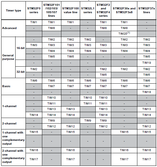
The timers in a STM32 micro can be classified as follows:
- Advanced Timers
- General Purpose Timers
- Basic Timers
Of these three types of timers the first two are common to all. The third is available only in larger variants. The number of timers of a given class also varies with the capacity or the size of the STM32 micro. For instance, STM32F103C8T6 has one advance timer while STM32F103VET6 has two advanced timers. STM32CubeMX can be used to determine which timers are available in a given STM32 micro unless you wish to get lost in piles of documentations.
In my own words, I will describe STM32 timer as follows.
General purpose (GP) timers have all the features of a typical timer-counter module. They are pretty much the same as the ones we have seen in most 8-bit micros. They can be used for any timer-counter-related purpose and so they are named as such. PWM generation, input capture, time-base generation and output compare are the basic uses of a GP timer. Typically in a STM32 micro you’ll find more GP timers than other classes of timers. Studying GP timers clears the basic concepts.
Basic timers are timers that don’t have I/O channels for input capture/PWM generation and so they are strictly used for time-base generation purposes. Basic timers are available only in large capacity STM32 micros and are the simplest of all timers.
Advanced timers are almost the same as GP timers but they additionally have the ability to generate complementary PWM signals as well as generate brake and dead-time for such signals. These features make them suitable for applications related to motor control, inverters, SMPSs and other power electronics-related tasks. In most STM32 micros, there is at least one such timer. In larger STM32s, there can be two.
Every timer in a STM32 micro is independent of the others and so they don’t share any common resource. The only things that are common are the register types, naming convention and their operating principles. With only a few exceptions, timer modules are more-or-less compatible amongst STM32 micro families. You’ll not find significant differences when you migrate from STM32F1xx series to STM32F4xx series. This is not true for other internal hardware like GPIO ports, ADCs, etc.
Timer Overview
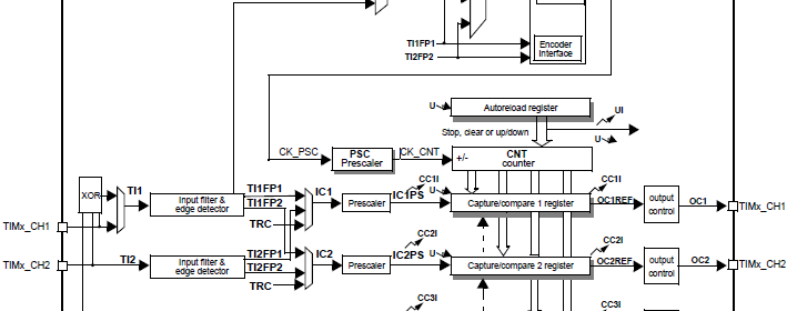
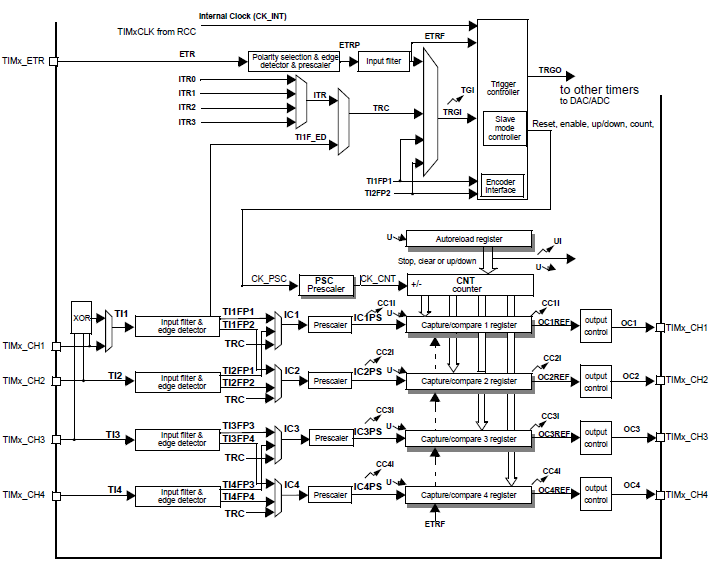
Typically most STM32 timers consist of a 16-bit auto reload counter and a 16-bit prescaler. The prescaler is responsible for dividing the incoming clock signal from a clock source as per our need. The auto-reload counter is loaded just we used to load timer registers of 8-bit MCUs. The only thing exceptional about it is its auto reloading feature. In old school 8-bit MCUs, we needed to reload the timer after every interrupt or after every overflow. This is not required in STM32s as it is automatically handled.
Unlike most other MCUs in which timers usually count incrementally, STM32 timers can count up, down or center-aligned. However in most applications up counting is more preferable over other methods.
With the exception of basic timers, all STM32 timers have four independent I/O channels (TIMx_CH1 – TIMx_CH4). These can be used as follows:
- Input Capture
- Output Compare or PWM
- One Pulse Mode
Timers can be clocked by:
- Internal Clock
- External Clock Sources
- External Mode 1 (TI1 and TI2 pins)
- External Mode 2 (ETR pin)
- Internal Trigger (ITRx)
Interrupt and DMA events occur when the followings occur:
- Update
- Counter overflow/underflow
- Counter initialized
- Others
- Trigger
- Counter Start
- Counter Stop
- Counter Initialize
- Others
- Input Capture / Output Compare
- Others
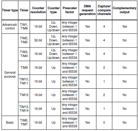
The table below summarizes some common features of STM32 timers.
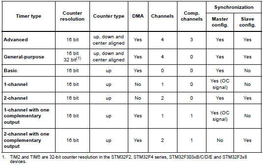
From all of these info we can draw the versatility of STM32 timers although they are not very easy to deal with in the beginning. This is why unlike my previous tutorials on other STM32 peripherals, we will study the timers concurrently with their applications and coding.
|
|
well done sir
How to set the PWM with Center aligned mode ?
Read this app note: http://www.st.com/web/en/resource/technical/document/application_note/DM00042534.pdf
Thanks,
Now need the sample code to change the CMS bits different from ’00’
Great tutorials! Best I’ve found so far.
Thanks…. 🙂
first of all i like to say a million thanks for this tutorial and i have been waiting for this
tutorial i am your biggest fan in stm32 programming for there is little information about it on the web you’ve motivated me to keep having interest in on knowing about the 32bit micros
Thanks…. People like you keeps me going…. 🙂
Pingback: STM32 Timers - Arduino collector blog