STM32 Timers
|
|
Timer Registers
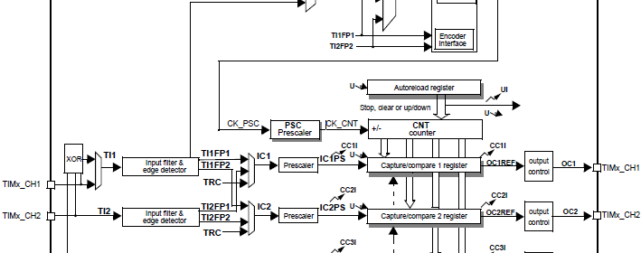
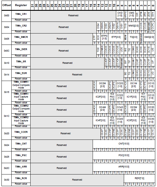
Before we start coding, I must point out that perhaps the most complex sets of registers in a STM32 micro belong to timer-counter modules. We don’t need all of them for a specific application and so to avoid complexity we will only discuss about those registers that we will be needing for a particular task. A few registers will always be needed but other will needed for specific tasks like input capture/ output compare. Another important thing to note on these registers is the fact that though all registers in an ARM micro are 32-bit wide, for timer modules and most hardware peripherals most of the bits are reserved. This makes handling them easy. To yet simplify handling these during coding I have used my own built definitions and functions similar to ST’s SPL. MikroC libraries also take care some of such. Just for reference check out the register map of any timer module. I have shown one below.

Design Considerations
A few things should be remembered before coding and designing hardware. These are as follows:
- Timer modules to be used should be enabled first by setting appropriate RCC_APBx_ENR register bits. Individual counters, DMA and interrupts are enabled after setting up everything else.
- Right after power on reset every bit of internal registers of a STM32 micro are in their default reset values. For timer registers the default is all zeroes, meaning everything disabled. Thus the ones we don’t need to use, need not to be forcefully cleared. Usually this is the case for most internal hardware peripherals. However if you need to change stuffs on the fly, you better reset all settings just to avoid running down to the jaws of a software bug or unprecedented results.
- Timers can’t be used like RTCs for a number of factors and so it is not always wise to use them as precision time keepers. If accuracy is not very important, timers can be used for general time-keeping purposes. No doubt timers are accurate than wasteful delay functions but they are not good as dedicated RTCs.
- When using GPIOs for capture/compare mode, make sure which I/O pins are being used because sometimes the I/O pins related to these functionalities can be remapped elsewhere. Use STM32CubeMX to find out which pins can be used with a given timer.
- AFIO block must be enabled and used for remapping I/O pins since capture/compare are alternative functions of ordinary GPIOs. AFIO block should be enabled even if remapping is not used. GPIOs should be configured as AFIOs for compare/output modes.
- When using input capture mode, be sure of the maximum input voltage level of an incoming waveform. Not all but most I/O pins are 5V tolerant. I will however strongly suggest not to cross the VDD limit, typically 3.3V. Similarly when using compare mode, be sure that the end device like a LED or an opto-coupler connected to a compare pin doesn’t draw too much current. Simply do not exceed the specified GPIO electrical specs. This is very important.
- The internal oscillator of STM32 micros are quite accurate (1% tolerant) but if more precision is needed, it is better to use well calibrated external clock generators or precise external crystals.
- Be aware of clock system prescalers, multipliers and clock sources.
- Remember APB2 bus peripherals can run at maximum system clock speed while APB1 bus peripherals are limited to half of that speed. Thus APB1 timers may not run at the same clock speed as the APB2 timers.
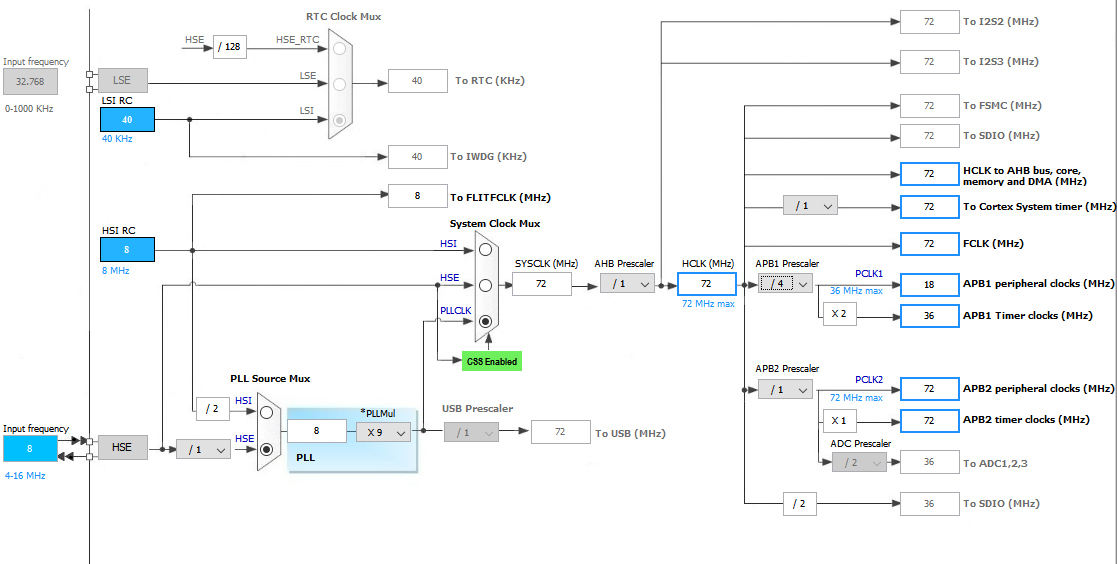
- Since internal clock speed of each timer is dependent on its APB bus speed, it is a must know to which APB bus a given timer belongs. On MikroE’s Timer Calculator utility software this is actually the MCU clock speed. Use STM32CubeMX and MikroC compiler’s project editor to determine APB bus speeds. I have shown an example below. Here APB1 timers are being fed with 36MHz while APB2 timers are being fed by 72MHz.
Hardware and Software
As with the previous issues, MikroC for ARM C compiler is what we will be using. Except the code examples which are dependent on MikroC compiler’s library functions, most of the codes can be ported to other compilers. We’ll also get introduced with a new software tool and obviously STM32CubeMx and ST-Link software will play their parts. I’ll also use my developed SPL libraries.
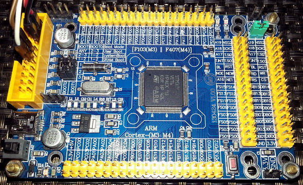
The hardware that I’ll introduce here is a STM32F103VET6 ARM Cortex M3 development board. I chose this micro as it has all types of timer I discussed, eight timers – two advance timers, two basic timers and four GP timers. In terms of all hardware resources, it is a beast that comes in a LQFP100 SMD package with 512kB of flash, 64kB of RAM and 82 I/Os. The board on which it is embedded is also neatly designed with proper readable labels – simply a nice STM32 development board.
|
|
well done sir
How to set the PWM with Center aligned mode ?
Read this app note: http://www.st.com/web/en/resource/technical/document/application_note/DM00042534.pdf
Thanks,
Now need the sample code to change the CMS bits different from ’00’
Great tutorials! Best I’ve found so far.
Thanks…. 🙂
first of all i like to say a million thanks for this tutorial and i have been waiting for this
tutorial i am your biggest fan in stm32 programming for there is little information about it on the web you’ve motivated me to keep having interest in on knowing about the 32bit micros
Thanks…. People like you keeps me going…. 🙂
Pingback: STM32 Timers - Arduino collector blog