Humidity and temperature measurements with Sensirion’s SHT1x/SHT7x sensors (Part 2)
|
|
In Part 1 of this tutorial, we discussed about Sensirion’s SHT1x and SHT7x series of humidity sensors, their interface specifications, the communication protocol used for transferring data in and out of the sensor, and the equations to convert their digital outputs to actual physical quantities. These sensors are capable of measuring temperature along with relative humidity and provide outputs in fully-calibrated digital words. We will now see how a PIC microcontroller can be programmed to communicate with these sensors, read the temperature and relative humidity data, and display the information on a character LCD.

Circuit setup on breadboard
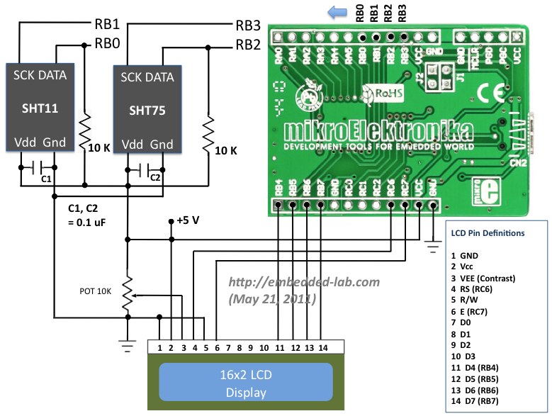
Circuit Diagram
We will be interfacing the SHT11 and SHT75 sensors simultaneously to different port pins of PIC18F2550 and display the measured values of relative humidity and temperature from both on a 16×2 character LCD. The two sensors are placed next to each other and are supposed to measure the same values for relative humidity and temperature. The circuit diagram below shows the connection of the two sensors and a 16×2 character LCD to StartUSB for PIC board. StartUSB for PIC is a small development board for PIC18F2550 from mikroElektronika. The microcontroller comes preprogrammed with a bootloader, and therefore, no external programmer is required.

Connecting a LCD and SHT sensors to StartUSB for PIC board
The LCD is operating in 4-bit mode, where the data pins D4-D7 are driven by RB4-RB7 pins of PIC18F2550. The RS and E pins are connected to RC6 and RC7 respectively. The clock lines of SHT11 and SHT75 are driven separately by RB1 and RB3 pins of PIC18F2550, respectively. On the other hand, the RB0 and RB2 pins are connected to the data pins (SDA or DATA) of SHT11 and SHT75, respectively. A decoupling capacitor (100 nF) is connected between Vcc and Gnd pins of each sensor. The PIC18F2550 microcontroller on-board StartUSB for PIC board runs at 48 MHz using the internal PLL along with an external 8.0 MHz crystal. A pull-up resistor of 10 K is required for each DATA line (in fact, the SHT11 board from mikroElektronika has pull-up resistors of 1 K on both DATA and SCK lines, but the manufacturer’s datasheet recommends 10 K).
Software
The sensor’s serial communication protocol was described in Part 1. We will implement it for PIC18F2550 using mikroC Pro for PIC. MikroElektronika provides a sample code written in mikroC for reading temperature and relative humidity from a SHT11 sensor. This code was later modified by Uroš Pešovi? (from Serbia) in order to account for the new conversion coefficients released by Sensirion for its version 4 sensors. I am adapting the same code for dual sensor case with some modifications that are required for our specific case.
The following subroutine is to reset the interface, in case the communication to the sensor is lost. In our case this routine will be always called before sending a new measurement command to the sensor. In order to pull the DATA line high, all you need is to define the direction of PIC port pin driving the DATA line as input. The pull-up resistor will then pull the line high. However, the same port pin direction must be defined as output and set to logic ‘0’ to pull the line low.
void SHT_Reset() {
 SCL = 0;                     // SCL low
 SDA_Direction = 1;           // Define SDA as input to pull the DATA line high
 for (i = 1; i <= 10; i++)    // repeat 18 times
 SCL = ~SCL;                  // invert SCL
 }
Once the connection is reset, you need to send a Start Transmission sequence. The subroutine for this would be something like this.
void Transmission_Start() {
 SDA_Direction = 1;            // Pull SDA high
 SCL = 1;                      // Clock high
 Delay_1us();                  // 1 us delay
 SDA_Direction = 0;            // SDA as output
 SDA = 0;                      // DATA low
 Delay_1us();                  // 1us delay
 SCL = 0;                      // Clock low
 Delay_1us();                  // 1us delay
 SCL = 1;                      // Clock high
 Delay_1us();                  // 1 us delay
 SDA_Direction = 1;            // SDA as input, DATA is high
 Delay_1us();                  // 1us delay
 SCL = 0;                      // SCL low
 }
As we discussed in Part 1 of this tutorial that the microcontroller is required to send an acknowledge pulse on receiving a data byte from the sensor, the following routine takes care of that.
void MCU_ACK() {
  SDA_Direction = 0;     // define SDA as output
  SDA = 0;               // DATA low
  SCL = 1;               // Clock high
  Delay_1us();           // 1us delay
  SCL = 0;               // Clock low
  Delay_1us();           // 1us delay
  SDA_Direction = 1;     // DATA high
 }
The following subroutine sends a measurement command to the sensor, then waits till the measurement is finished, and finally receives the two byte measurement readings.
long int Measure(short command) {
  j = command;                  // j = command (0x03 or 0x05)
  SHT_Reset();                  // Reset interface
  Transmission_Start();         // procedure for sTmprting transmission
  k = 0;                        // k = 0
  SDA_Direction = 0;            // define SDA as output
  SCL = 0;                      // SCL low
  for(i = 1; i <= 8; i++) {     // repeat 8 times
    if (j.F7 == 1)              // if bit 7 = 1
     SDA_Direction = 1;         // make DATA line high
    else {                      // else (if bit 7 = 0)
     SDA_Direction = 0;         // set DATA line as output and
     SDA = 0;                   // pull DATA line low
    }
    Delay_1us();                // 1us delay
    SCL = 1;                    // SCL high
    Delay_1us();                // 1us delay
    SCL = 0;                    // SCL low
    j <<= 1;                    // move contents of j one place left
                                // until all 8-bits of command are sent
   }

// Wait until the DATA line is pulled low by the sensor
   SDA_Direction = 1;           // define SDA as input
   SCL = 1;                     // SCL high
   Delay_1us();                 // 1us delay
   SCL = 0;                     // SCL low
   Delay_1us();                 // 1us delay
   while (SDA == 1)             // while DATA is high, do nothing
   Delay_1us();                 // 1us delay

// Read 2 bytes of measurement data after it is ready
  for (i = 1; i <=16; i++) {    // repeat 16 times
    k <<= 1;                    // move contents of k one place left
    SCL = 1;                    // SCL high
    if (SDA == 1)               // if DATA is high
     k = k | 0x0001;            // set the corresponding bit of K to 1
    SCL = 0;
    if (i == 8 )                 // Send an acknowledge after each byte
     MCU_ACK();
   }
  return k;                     // Return the measurement data
  }
Once you get the two-byte measurement output from the sensor, you can use the conversion coefficients provided in the datasheet to retrieve the temperature or relative humidity. This part is just a mathematical manipulation and hence not described in here. The complete code for this project is however, downloadable from the link provided below.
Download complete mikroC project files
Important note
The datasheet recommends to use a 10K pull-up resistor to the DATA line, and the SCK line may work fine without a pull-up resistor. However, the SHT11 proto board from mikroElektronika has got two 1 K resistors to pull-up both SCL and SDA lines. The resistors dissipate some heat when the lines are pulled low. This may introduce error in the measurement of both temperature and relative humidity, as the resistors are in the close proximity of the sensor as all of them are on the same board. In order to minimize this heat dissipation, the port pins of microcontrollers that drive SCK and SDA lines, must be defined as input pins, while in idle state. If you leave them as outputs with logic 0 states, there will be current continuously flowing through the pull-up resistors, which will dissipate more heat and raise the temperature of the sensor.
Output
The picture below shows the two sets of temperature and relative humidity readings shown on the LCD, which were measured by SHT11 and SHT75 sensors. The temperature values are consistent within 0.1 °C. However, the SHT11 seems to be off from SHT75 by 1.2 % in the measurement of relative humidity. These readings are taken right after the circuit is powered on.

Temperature and relative humidity readings from two sensors
The sensors are scheduled to take the measurements in every 2 sec. Because of heat dissipation in the resistors on-board, the temperature measurement from SHT11 module slowly increases and drifts apart from that of SHT75.

SHT11 drifting apart from SHT75 because of heat dissipation
The drifting of SHT11 becomes more severe if you don’t change the SCK pin direction to input while it is in idle condition. See the picture below where the SHT11 measurement of the temperature is more than 2 °C higher than that of SHT75. This drift occurred within less than first two minutes after the circuit is powered on. Here, you can also see the inverse relationship between temperature and humidity. With increasing temperature, the relative humidity is decreasing.

Temperature of the SHT11 module increases significantly due to power dissipation in the pull-up resistors during idle conditions
Conclusion
Sensirion’s SHT series of humidity sensors are very handy in measuring both relative humidity and temperature because of on-board signal processing and providing fully calibrated digital outputs. They communicate with a host controller through two wire serial bus: DATA and SCK. The DATA line requires an external pull-up resistor that dissipates some power as heat when the DATA line is pulled low. Therefore, care must be taken, specially for surface mount type sensor like SHT1x, in placing the resistor along with the sensor on the same module. The port pins of the microcontroller driving the clock and data lines must be set as input during idle conditions to minimize the heat dissipation in the pull-up resistors.
References:
- Datasheets of SHT1x and SHT7x humidity sensors
- http://www.mikroe.com/forum/viewtopic.php?f=88&t=30426
Further suggestions
SHT1x/7x sensors cannot measure dew point directly, but it can be derived from the humidity and temperature measurements. The datasheet provides the equation and necessary coefficients required to calculate dew point. There are some other details such as the stability of sensor, normal operating conditions, wiring considerations, etc. that are not discussed here, but readers can find those information in the datasheet.
|
|
Hi,
The SHT1x and SHT7x are obsolete at this time. I have an SHT31 that I’m trying to interface with a PIC18F2420. The SHT31 uses I2C protocol. Was this project using SPI mode or I2C mode? I’m wondering how much of the code needs to be modified to accommodate the SHT31. Any help would be appreciated.
Thank you.
hi there, i need some help from u
Im using SHT1X sensor with XMEGA32a4
Im able to read the vale and display it
But my problem is, suppose the temperature is 29C, its start readiing as 29.0C, 29.4C, 29.9C, 30.2C, 31.4C …….
its increases.
hi, can u share ur Xmega code… ?
thanks
I have a doubt that instead of using the void start(), void stop()…..function can we use I2C1_START(), I2C1_STOP() functions…….
please. may i know your schematic diagram ? i want to see your connections.
Hi
I am using PIC 18f4550, the temperature readings are always 40.1C if I define the data and Clock which is SDA connect to RB0 and SCL connect to RB1
I am using the same code you post it . can you please help, should I modify any commend to work with pic 18f4550 .I am using mikroc pro code and Proteus circuit simulation, thanks for the great explanation and help
Hello Rajendra,
I am impressed by your talent in electronics diy. We recently developed a type of wireless sensor transmitter module DRF5010S. It can collect the data of SHT1x, SHT21 and SHT25 sensors without extra MCU needed. If you have interest, please check the link below for more details:
http://www.dorji.com/pro/Modules/Wireless_sensor_module.html
Certainly if you need samples to play with, just email me or leave a message here.
Hi,
i am using pic 18f4520, the temperature readings are always 40.1C if i define the data and serial ports with Latch and if i define them as RC0, RC1, the code stucks at while (SDA1 == 1), can you please help, should i modify any loop counts for compatibility? i can send you my mikroc code and Proteus circuit simulation but i dont have your email, please contact me if possible, thanks for the great explanation provided…
Mohammed,
My email address is in the Contact link at the top.
Hi,
Which software do you use to create a so cool Circuit Diagram ?
@PICfans,
I use MS Powerpoint.