LM386 based stereo audio amplifier with digital volume control
|
|
Due to its simplicity (requires minimum external components) and high availability, LM386 is very popular among hobbyists for use in low-voltage audio amplification applications. Most of the time a potentiometer is used at the input side of LM386 to provide a volume control in the output speaker. The potentiometer does not control the gain of the amplifier itself, but it creates a voltage divider network at the input, which in fact controls the fraction of the audio signal that is fed to the amplifier. This project is about a stereo audio amplifier using two LM386 ICs with digital volume control for both left and right speakers. So, how would you control the volume digitally? You are right, by replacing the traditional electro-mechanical form of potentiometers with digital potentiometer chips. This project uses MAXIM’s DS1868 dual digital potentiometer chip and a PIC microcontroller to control the volume of a stereo output from two LM386 ICs.

Stereo audio amplifier with digital volume control
Theory
Tons of resources can be found on the internet about LM386 and so I am not going to describe it in detail here. The LM386 IC has got 8 pins which require very few external components to work as a mono amplifier. The circuit below is taken from the datasheet and shows the external components required for constructing a mono-channel audio amplifier with LM386. An external 10K potentiometer at the input is used to control the volume of the output speaker. For a stereo audio amplifier, we need two of this circuit.

LM386 audio amplifier circuit
The supply voltage range for LM386 is wide (4-18 V). It can be powered with a +9V PP3 battery. For digital volume control feature, we will replace the external 10K potentiometer at the input stage with a digital potentiometer chip. MAXIM’s DS1868 is a dual digital potentiometer chip. Each wiper terminal has 256 positions between the high and low end of the potentiometer. The wiper position is set by an 8-bit control value that is stored into the I/O register of DS1868. The communication with the host microcontroller is done through a 3-wire serial interface. Please read my previous post, ‘How to interface MAXIM’s DS1868 digital potentiometer with a PIC microcontroller‘ for further detail on DS1868.
The block diagram below shows the operation of the stereo audio amplifier with separate volume control for left and right speakers. The DS1868 has two potentiometers and therefore a single chip is enough for two LM386 circuits. The DS1868 is offered in three standard resistance values: 10, 50, and 100 K? versions. I am using DS1868-010, which is the 10K version. The stereo audio is fed to the high ends (H0 and H1) of the two potentiometers, while both the low ends are grounded. The input audio signals for the two LM386 stages are derived from the wiper terminals (W0 and W1). The PIC18F2550 microcontroller receives user inputs from tact switches and set the wiper positions accordingly, which in fact control the output volume. A LCD is used to display the individual channel volume level.

Block diagram of stereo audio amplifier with digital volume control
Circuit Diagram
The block diagram provided in the the theory section described how this project works. The stereo audio amplification circuit is made up of two LM386 mono amplifiers. The circuit diagram of LM386 based mono amplifier was also described above. The microcontroller, DS1868 digital potentiometer, LCD and tact switches connections are shown below. I am using the StartUSB for PIC board for this project which has got a PIC18F2550 microcontroller loaded with a fast USB bootloader. However, this project can also be done with a smaller size PIC from the mid-range family.

Circuit diagram of digital volume control unit for LM386
There are three tact switches for user inputs. They are named UP, DOWN, and SELECT in the circuit diagram. UP is to increase and DOWN is to decrease the volume. With the SELECT input, you can set the volume of left and right speakers jointly or individually. As mentioned earlier too, the stereo input is fed to the H0 and H1 pins of DS1868, whereas the L0 and L1 pins are grounded. The two wiper terminals, W0 and W1, are connected to the input pins of the two LM386 mono amplifiers. The LCD is operated in 4-bit mode and the data pins (D4-D7) are connected to RB4 through RB7 port pins. The two LCD control pins, RS and E, are driven by RC6 and RC7 pins of PIC18F2550.

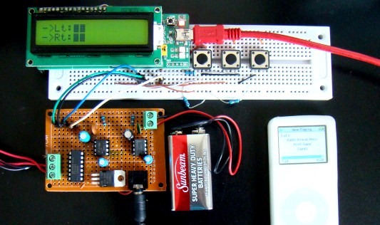
Circuit setup
Software
The firmware for PIC is developed in mikroC Pro for PIC compiler. It’s a test version where I have set 10 volume levels from 0 to maximum, with the step size of 25 for the potentiometer wiper position. But you can further reduce the step size, say to 5. That will give you 51 discrete volume steps from 0 to maximum. Every time you press UP or DOWN button, the output volume will go increase or decrease with a constant amount, which corresponds to the step size. You can select individual or both channels (left and right speakers) for UP and DOWN operations.
Download the source code and HEX file for this project
Output
Enjoy watching the video at the end of the article that shows the stereo audio amplifier in action.

Audio amplifier with speakers

Digital volume control for left and right speakers
The audio recorded in this video may not sound like stereo because my camera did not have that feature. But this technique of digitally controlling the volume of individual channel of stereo output works great.
|
|
Sir DTH me aavaj nhi aa rhi
Dear writer! I’m sorry for the feedback I wrote earlier. Your scheme and firmware are working well. Please accept my words of gratitude and wish you good luck in your work. Translated into English with bing.com
Dear Author! I apologize for the feedback I have written earlier. There was not a big mistake in the wiring on my side. Your scheme and firmware work great. Accept my words of gratitude and wish you good luck in your work.
Dear author! It was not clear for whom uploaded your project. You have removed from the source code and hex files initialize controller and display. If you’re relying on users who can write firmware for microcontrollers, so they themselves will write the firmware without looking at your site. If your kindness extends to users not versed in the microcontroller code, then they will not be able to run your project. Therefore, I ask you to lay out ready hex file, as you stated in your article-pic 18F2550 and LCD HD44780. I think people will thank you. Thank you in advance. Yours faithfully Oleg. P.s. sorry for English. Translated by using Bing.
Source and Hex files are all included in the link provided in the Software section.
You have used amplifier with gain of 200.
If +5v is max in project does this mean that max Voltage input to amplifier (pin 3) should be 25mV?
Is this project ok for small speakers for small electronics project, rather than PC type speakers?
Thanks
It should work for small speakers.
Software with scheme does not operate!
another thing sir, do i need to buy a startusb for pic? or is it ok to use directly the pic18f2550?
Good day sir, i would like to ask if ds1867 would be a suitable replacement for ds1868? and would it be okay to use a different type amplifier?
also may i interface and program with microcontroller 8051
hi sir, can you give me coding for this project???
Hello admin, i found this post on 24 spot in google’s search results.
You should reduce your bounce rate in order to rank in google.
This is major ranking factor nowadays. There is very handy wordpress plugin which can help you.
Just search in google for:
Lilas’s Bounce Plugin
Greetings!
Great idea!
Can I have the PIC stored in memory in the current set positions, reading is switched back to the value set to the shutdown? If so, would add to the C code for it? 😉
Respect.
Gran proyecto. Se podría hacer pero quitando la pantalla?
Hey, nice project! Beatifully done, and a great idea to give a new twist to the old LM386 (I used that chip for my very first audio project something like 20 years ago).
Did you find any problems by sendind audio directly to the digital pot? I am worried about how much signal these little things can handle. They look quite fragile, and by their datasheets we are talking about no more than 2mA of constant drain.
Do you have any research about input levels?
Thanks,
Wally
instead of pressing up and down button is it possible to control by sending the digital values to the DS1868 ?
if possible why up and down buttons ?
hello, my name is Evanildo, I am Brazilian, I live in São Paulo, I saw your work, your projects is very cool.
can you tell me who is the composer of this beautiful song, which you use to demonstrate the project volume control?
I’m sorry I do not speak English I’m using an electronic translator.
It is from one of Dean Martin’s songs: http://www.youtube.com/watch?v=TQ7Jna_HW8c
The instrumental version can be found here: http://www.youtube.com/watch?v=0y47nAJAPwU
hello, my name is Evanildo, I am Brazilian, I live in São Paulo, I saw your work, your projects is very cool.
can you tell me who is the composer of this beautiful song, which you use to demonstrate the project volume control?
I’m sorry I do not speak English I’m using an electronic translator.
Thank you 🙂
This is actually a very fantastic Idea and good use of the lm386. Wao this idea will also work. Nice job.
Hi! Thanks, good proyect.
HI AM HAPPY OF YOUR DESING N I WANT TO BUILD IT ,SO CN U GIVE ME A FULL SCHEMATIC DIAGRAM WITH INPUTS AND LM386 AND PLEASE TELL ME YOU USING WCH SOFTWEAR TO RUN YOUR PROGRAM, THANK U.
woooow !!
Hi!
Thanks for the great tutorial. Can you please tell me if there is a distance limited over which this will work over i.e. 5 meters/10 meters, etc? We plan to use this in a commercial jukebox to control the volume from behind the bar.
Finally, is there somewhere you can buy a ready made version of this off-the-shelf as my electronics knowledge is extremely limted 🙁
Many thanks
i love your site but i’ll love you to send the complete circuit diagram of the amplifier with digital display. thanks for your concern.
Hello,
I can’t seem to find an alternative chip for DS1868. Maybe because I’m too lame for research. I was hoping if you could give me some advice for alternatives? Thank you 🙂
Again can u pls email me a full schematic diagram for this project, I realy like diong it. Thanks
Hi! Can u pls help, I can not find both DS1868 and PIC18F2550. What could be the replacements
what speakers u r using???n and for interfacing u used SPI or I2C ???
The speakers are 8Ohm type and communication interface is 3-wire as described here: http://embedded-lab.com/blog/?p=2969
i m working on the same project..there is a transistor on the pcb board…but not in the ckt diagram….whats its use…??
The transistor in the board is actually a LM7805 regulator that derives +5V for microcontroller from a 9V battery.
Pingback: Using PIC 18F4550 to make a digital potentiometer.
Hello, i would like to know how did you connect pins 1,2,3,5 to the start usb board.i understood that pin nr 1 and 5 are gnd pins on the start usb board.and the rest where exactly should they be connected because i cannot understand the datasheet…please help.thank you.
The pin numbers shown on the circuit diagram are of PIC18F2550, and not of the StartUSB board. I would suggest to use the pin names instead, such as RA0. RA1, and RA2 go to pus switches, and so on. The pin names are printed on the StartUSb board.
it is very nice ,the project of me in coll age is design digital volume control with audio amp,couldyou up load the introduction or discussion or other wise about it please.
Pingback: Variable resistor using Microcontroller
pls can you upload the circuit schematics or mail it to me. Thanks
can i used without pic18f2550 StartUSB board and
Hello, congratulations for the project!
I have a question, what should I modify the software for 25 steps of potentiometer?
Thank you.
Antonio
Hello, congratulations for the project!
I have a question, what should I modify the software for 25 steps of potentiometer?
Thank you.
Antonio
again am thankful
thank you first, second can we use a PIC18F4550 instead of 2550 ? if yes what are the modifications that should be made ?
Ali,
Yes, you can use any other microcontroller, but you have to modify the code accordingly. Read the datasheets of two and you will see if what differences would be there.
another questions please , if i programmed the PIC for the first time , should i program it every time i would used the device ?
The USB port on the board is to program the microcontroller and is not exactly the part of the project. If you program the PIC once, it is saved into its program memory which is non-volatile, and so you don’t need to reprogram it every time.
hello,
may i ask about purpose of the USP port … is it obligatory to use it ? and how can i implement it in the circuit since its implementaion is not showen in the diagram you provided above
Hello,
This is an interesting project and I would like to build it.
I have two questions:
What is the part number of the LCD display?
I have seen that there are different DS1868 with values of 10k, 50k and 100k. Which one have you used?
Thanks.
I am using 10K value, and the display is any HD44780 based 16×2 character LCD.
There are other ICs superior to LM386 that require less components. For example: TDA7052. The LM386 is just more popular because it is older and just works so people are used to it.
can the DS1868 be used without PIC? i’m planning to use it in my portable amplifier hence lcd is not needed at all
if it can be used, how do we do the wiring for up & down switches?
Iskandar,
No, DS1868 cannot be used with simple up and down switches. There are some other digital potentiometers that do have that features. You can search on google.
Pingback: Make Electronics stereo audio amplifier with digital volume control | Make your own Electronics project
Hey RB! Greetings! Just to let you know, I am a big fan of your blog. And to spread the love, I am adding a link to your blog on Durofy – my own little site. You should visit us sometime. Good Luck!
Thanks, Rishab! You have got some good stuff there, I liked it.
Thanks.
Hi sir,
How did you get that DS1868 chip?
Thanks
I got some free samples from MAXIM.
may u give the step wise process about how to program DS1868
Pingback: Electronics-Lab.com Blog » Blog Archive » Digital volume control for a stereo audio amplifier
Pingback: Stereo amplifier with digital volume control | You've been blogged!
Pingback: Stereo amplifier with digital volume control - Hack a Day
Hello RB,
Great Project!
I’m going to built it.
Any equivalent DP chips beside DS1868 as???
@meguitarist
There are varieties of digital potentiometer chips manufactured by MAXIM and other companies (Microchip, Analog Devices, etc). Check their websites for detail.